


CIRCUIT DESCRIPTION
3-28
February 2001
Part No. 001-9800-001
For example, if current through R207 attempts to
increase, the emitter voltage of Q200 decreases. Q200
then conducts less and turns Q201 off slightly to main-
tain a constant bias current. This provides a stable bias
over changes in temperature.
The output signal of Q201 is fed to another band-
pass filter similar to the one on the input described in
the preceding section. Impedance matching with the
filter is provided by a section of microstrip on the
collector and C227. Resistor R209 lowers the Q of the
microstrip to make it less frequency selective. C222-
C226 decouple various unwanted AC signals from the
circuit.
3.11.3 FIRST MIXER (Q202), CRYSTAL
FILTER (Z204)
The signal from Z201 is then applied to mixer
Q202. A 3-dB pad on the output of Z201 formed by
R215-R217 sets the input level to the mixer. Imped-
ance matching between the pad and mixer is provided
by a section of microstrip and C245.
Q202 is biased by constant current source Q203
similar to Q200 described in the preceding section.
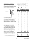
The injection signal is applied to the emitter of Q202
and is at a level of approximately 10 dBm. With 800
MHz models, the injection frequency is 52.950 MHz
below the receive frequency, and with 900 MHz
models, it is 45 MHz below the receive frequency.
Filtering of the injection signal is provided by two-
pole bandpass filter Z203. With 800 MHz models, it
has a center frequency of 807 MHz and a bandwidth of
18 MHz; and with 900 MHz models, it has a center
frequency of 893 MHz and a bandwidth of 6 MHz.
The 52.950 or 45.000 MHz output signal of mixer
Q202 is then applied to crystal filter Z204. Impedance
matching between Q202 and 50-ohm, 3 dB pad R210-
R212 is provided by L220, C231, and C232. Resistor
R214 lowers the Q of L220 to make it less frequency
selective. Matching between the pad and Z204 is
provided by C265, C266, C268, and L213.
Z204 is a four-pole crystal filter. With 800 MHz
models it has a center frequency of 52.950 MHz and a
-3 dB bandwidth of 15 kHz, and with 900 MHz
models it has a center frequency of 45 MHz and a -3
dB bandwidth of 7.5 kHz. This filter attenuates wide-
band noise, adjacent channels, frequencies resulting
from intermodulation, and other undesired frequen-
cies. Impedance matching between this filter and
U201 is provided by C271, C272, L215, and R228.
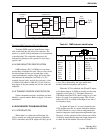
3.11.4 SECOND MIXER/DETECTOR (U201)
Introduction
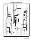
U201 contains second mixer, IF amplifier,
detector, RSSI, and audio amplifier stages as shown in
Figure 3-6 on page 5-18. The IF signal is applied to
pin 1 which is the input of an internal IF amplifier
stage.
Second Mixer
From the IF amplifier the signal is internally fed
to the mixer which combines it with the 52.500 MHz
(800 MHz models) or 44.550 MHz (900 MHz models)
second injection frequency to produce a second IF of
450 kHz.
The injection frequency on pin 4 is produced by
tripling the frequency of reference oscillator U806. To
do this, part of the reference oscillator signal is applied
to tripler Q207. This stage is an amplifier with the
output tuned for the third harmonic of the reference
oscillator frequency. This output tuning is provided by
a two-pole bandpass filter formed by L219, C287,
C288, L217, and C290. The output level of this filter
is approximately 0.25 V rms.
Ceramic Filters (Z202/Z206, Z205)
The 450 kHz output of the internal mixer is fed
out of U201 on pin 20 and routed to ceramic filter
Z202 for all 900 MHz and 800 MHz narrow-band
(12.5 kHz) channels, or Z206 for 800 MHz wideband
(25 kHz) channels. Z202 has a nominal bandwidth at
the –3 dB points of 8 kHz, and Z206 has a bandwidth
of 15 kHz. The function of these filters is to attenuate
wideband noise present in the IF signal.
Routing of the IF signal to the appropriate filter is
provided by Q205 and Q206, PIN diodes CR207-
CR210, and several resistors and capacitors. It is
controlled by the microcontroller through the Q4
output of shift register U800. This output is low for
narrow-band channels and high for wideband
channels.
800/900 MHz RECEIVER DESCRIPTION