


CIRCUIT DESCRIPTION
3-4
February 2001
Part No. 001-9800-001
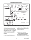
3.3 AUDIO/LOGIC BOARD DIGITAL CIRCUIT
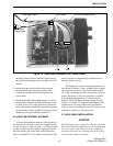
3.3.1 MICROCONTROLLER (U101)
General
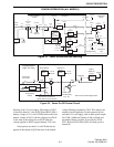
The control logic is based on an MC68HC11F1
eight-bit microcontroller (U101). This device has an
internal 1K-byte static RAM and 512-byte EEPROM
but no internal ROM or EEPROM. Therefore, all
program memory is contained in the external flash
memory device (U108). In addition, the microcon-
troller has several general purpose input and output
pins, an eight-channel A/D converter, and synchro-
nous (SPI) and asynchronous (SCI) serial ports. The
A/D converter port allows analog signals to be moni-
tored such as the power amplifier temperature, RSSI
signal, and vehicle battery voltage.
Separate buses are used for data and memory
addressing. The data bus consists of D0-D7, and the
address bus consists of A0-A15. The operating speed
of the microcontroller is set by crystal Y100. The 9.38
MHz frequency of this crystal is divided by an internal
divider to produce a lower internal operating
frequency.
Memory
The operating program and most of the person-
ality information used by the microcontroller is stored
in 128K x 8 Flash EPROM U108. The use of a Flash
memory device allows the program to be conveniently
updated using the standard programming setup and
special Flash programming software. This eliminates
the need to replace the microcontroller or a memory
device such as an EPROM. To reprogram the Flash
device, the microcontroller is placed in a special boot-
strap mode by turning power on with the MODA/
MODB inputs pulled low. This is done by the RPI by
applying 20 volts to the PTT pin of the microphone
jack.
Radio tuning information is stored in the 512-
byte EEPROM in microcontroller U101. External 4K
x 8 EEPROM U102 is used in high tier and data
models to store additional personality information. An
EEPROM can be programmed many times, does not
require a constant power supply, and retains data
indefinitely.
Temporary data storage is provided by an internal
1K x 8 RAM in microcontroller U101 and by external
8K x 8 RAM U107. These devices are used as a
“scratchpad” during program execution.
Reset
The microcontroller resets when power is turned
on and also when the 5-volt supply drops below the
normal range. Reset clears several internal registers
and restarts the operating program. This prevents
improper operation which may result during low -
voltage conditions.
The microcontroller resets itself automatically for
4064 clock cycles when power is applied to the VCC
input. Low-voltage reset is triggered by low-voltage
sensor U100. When the 5-volt supply drops to approx-
imately 4.25 volts, the RESET output goes low. This
resets the microcontroller and also inhibits operation
for as long as it is low. The microcontroller also has
internal reset circuits which trigger reset if problems
occur with the clock signal, illegal op codes, or the
watchdog timer circuit.
Reset is also triggered when the transceiver is
Flash programmed. A low pulse is created by C363
and R421 when the MODA/MODB inputs of the
microcontroller are pulled low to initiate this program-
ming. This automatically places the microcontroller in
the flash programming mode. However, reset does not
occur when flash programming is complete, so power
must be turned off and then on again to resume normal
operation.
Data Bus
A bi-directional data bus consisting of D0-D7 is
used to transfer data in and out of the microcontroller.
It is used to transfer parallel data in and out of memory
chips U107 (high tier only) and U108, and also
program latches U110-U112. The logic level on the
R/W
pin determines the direction of data on the data
bus. If it is high, data is read into U101, and if it is
low, data is written out. The E output goes high to
indicate when data on the data bus is valid or when an
external device can place data on the data bus.
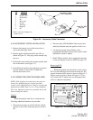
AUDIO/LOGIC DESCRIPTION (ALL MODELS)