


CIRCUIT DESCRIPTION
3-32
February 2001
Part No. 001-9800-001
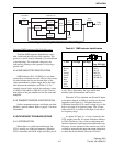
Over Current Shutdown
Current to the second and third amplifier stages in
power module U600 on the PA board is monitored by
sensing the voltage drop across R601. Pins 5 and 6 of
U500B are effectively connected across this resistor.
As current increases, the voltage on U500B, pin 6
decreases which causes the output voltage on pin 7 to
increase. The gain of each U500B input is set at about
ten by R509/R504 and R502/R507.
Emitter biasing for Q501 is provided by R506 and
R511. Normally, the output voltage of U500B is not
high enough to turn on Q501. However, if current
becomes excessive, for example because of an antenna
mismatch, Q501 begins turning on. This decreases the
base voltage of Q502 which turns off Q500 slightly
and cuts back power output. Over-current shutdown is
disabled in 15-watt models because CR500 is not used.
800/900 MHz TRANSMITTER DESCRIPTION