


CIRCUIT DESCRIPTION
3-9
February 2001
Part No. 001-9800-001
The passband of this filter is controlled by the Q1
output (pin 18) of latch U111. When LTR or digital
Call Guard data or low-frequency Call Guard tones are
received, this output goes high which turns Q300 on.
This switches additional capacitance into the circuit
and the filter cut-off frequency decreases to approxi-
mately 150 Hz. Then when high-frequency Call Guard
tones are received, the output goes low and turns Q300
off. This increases the cut-off frequency to approxi-
mately 220 Hz.
From U300C the data signal is fed to a DC resto-
ration circuit formed by U300D and U300A. This
circuit converts it from an analog signal floating at half
supply to a digital signal at 0 and 5 volt levels that can
be detected by the microcontroller. U300D is a stan-
dard noninverting amplifier with a gain set by R308,
R316, and R317 (R317 is AC grounded by C309).
Two attenuation levels are selected by gate
U307D similar to gate U307B described in Section
3.4.1. When wideband (25 kHz) channels are selected,
the control input (pin 12) of U307D is high and R317
is effectively shorted which increases gain. The gain
of U300D is approximately 3 with wideband channels
and 2 with narrow-band channels. This compensates
for excess amplification of the data signal in the
narrowband mode by U301B.
The CR301 diodes charge and discharge C309 to
establish a DC reference on pin 2 of comparator
U300A. This reference voltage is the average of the
positive and negative alternations of the data signal.
When pin 3 of U300A rises above the reference on pin
2, the output goes high (8 volts) and vice versa.
Voltage divider R304/R311 provides the 5-volt level
required by the microcontroller.
3.4.4 SQUELCH CIRCUIT (U304A, U304B)
The microcontroller uses the output from the
squelch circuit and also the RSSI output of the limiter/
detector (see Section 3.8.4) to determine when to mute
and unmute the receive audio and also when valid data
may be present. The squelch circuit is controlled by
the amount of noise present in the receive audio signal.
When no signal or a weak signal is being received,
there is a large amount of noise present. Conversely,
when a strong signal is received, there is very little
noise present.
The receive audio, data, and noise signal from
amplifier U301B is applied to a bandpass filter and
amplifier formed by U304A and other components.
This stage attenuates voice frequencies and LTR and
Call Guard signaling so that only noise frequencies in
the range of approximately 7-8 kHz are passed. The
output signal of U304A is applied across a resistor
network which sets the input level to a rectifier. Ther-
mistor R318 provides temperature compensation of
this network.
C304 charges through the forward biased diode in
CR300 and discharges through R306. C303 discharges
through the other diode in CR300. When the voltage
on pin 6 of comparator U304B rises above the refer-
ence on pin 5, the output goes low. For example, when
received signal strength is low, more noise is rectified
which causes the voltage on pin 6 of U304B to
increase and the output on pin 7 to go low (squelched
condition). A voltage divider formed by R416 and
R417 reduces the 8-volt output of U304B to the 5-volt
level required by the microcontroller.
The squelch threshold level is set by a D/A
converter formed by shift register U305 and several
resistors. The eight-bit output of U305 can control the
reference voltage applied to U304B in 256 steps. U305
is programmed by the SPI serial port described in
Section 3.3.1. R310 provides hysteresis to the
threshold level to prevent intermittent squelching
when receiving a weak or fading signal.
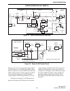
3.5 TRANSMIT AUDIO/DATA PROCESSING
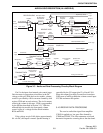
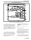
NOTE: A block diagram of the audio and data
processing circuitry is shown in Figure 3-3.
3.5.1 MICROPHONE AMPLIFIER (U303B),
HIGH-PASS FILTER (U303C)
The microphone audio signal is coupled by C349
to amplifier U303B which provides a gain of approxi-
mately two. R410, R414, and C354 provide a bias
voltage of approximately 3.2 volts on the nonin-
verting input. An 8-volt supply voltage to the micro-
phone amplifier is provided by R401, C348, and R406.
From U303B the microphone signal is coupled by
C350 to a high-pass filter formed by U303C and
several other components. This filter attenuates
AUDIO/LOGIC DESCRIPTION (ALL MODELS)