


SERVICING
4-3
February 2001
Part No. 001-9800-001
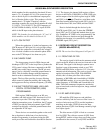
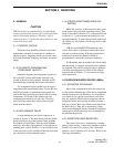
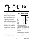
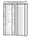
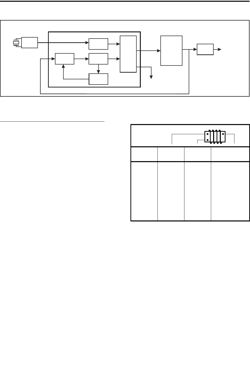
Figure 4-1 Simplified Synthesizer Block Diagram
Q801
Module
U806
14.850 MHz
TCXO
Reference
Counter
N
Counter
Prescaler
Control
¸ 64/65
Prescaler
Phase
Detector
VCO
Control
VCO
Buffer
Amplifier
U804
Synthesizer IC
Lock
Detect
fR
fV
To Rx
and Tx
Tantalum SMD Capacitors (P.N. 510-26xx-xxx)
Tantalum SMD capacitor identification varies
with vendor and physical size of the capacitor. The
positive (+) end is usually indicated by a colored band
or beveled edge. The value and voltage may be
indicated by printing on the capacitor or by using a
special code.
4.2.4 SMD INDUCTOR IDENTIFICATION
SMD inductors (P.N. 542-9000-xxx) use three
colored dots to indicate the value. The two dots on the
left side indicate the first and second digits of the
value in nanohenries, and the single dot on the right
side indicates the multiplier (see Table 4-2). For
example, brown, black, and red dots indicate a value
of 10 nH x 100 which is 1000 nH (1.0
µH). The last
three digits of the part number are also the value and
multiplier.
4.2.5 TRANSISTOR/DIODE IDENTIFICATION
Surface mounted transistors and diodes are iden-
tified by a special number. Refer to page 6-1 for more
information.
4.3 SYNTHESIZER TROUBLESHOOTING
4.3.1 INTRODUCTION
When there is a synthesizer malfunction, the
VCO is usually not locked on frequency. When the
VCO is unlocked, the LOCK output on U804, pin 18,
is low. This is detected by the logic which then
disables both the transmitter and receiver.
When the VCO is unlocked, the fR and fV inputs
to the phase detector in U804 are usually not the same
frequency (see Figure 4-1). The phase detector in
U804 then causes the VCO control voltage to go to the
high or low end of its operating range. This, in turn,
causes the VCO to oscillate at the high or low end of
its frequency range.
As shown in Figure 4-1, a loop is formed by the
VCO and the prescaler, N counter, and phase detector
in U804. Therefore, if any of these components mal-
function, improper signals appear throughout the loop.
However, correct operation of the counters can still be
verified by measuring the input and output frequencies
to check the divide number. Proceed as follows:
Table 4-2 SMD Inductor Identification
Color 1st Digit 2nd Digit
Multiplier
(Last PN Digit)
Black 0 0 1 (7)
Brown 1 1 10 (8)
Red 2 2 100 (9)
Orange 3 3 1000 (0)
Yellow 4 4 10,000 (1)
Green 5 5 100,000 (2)
Blue 6 6 ---
Violet 7 7 ---
Gray 8 8 ---
White 9 9 0.1 (6)