


Clarity - INT9 A/D converter Tables and specifications
32
5 Tables and specifications
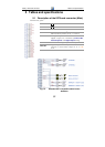
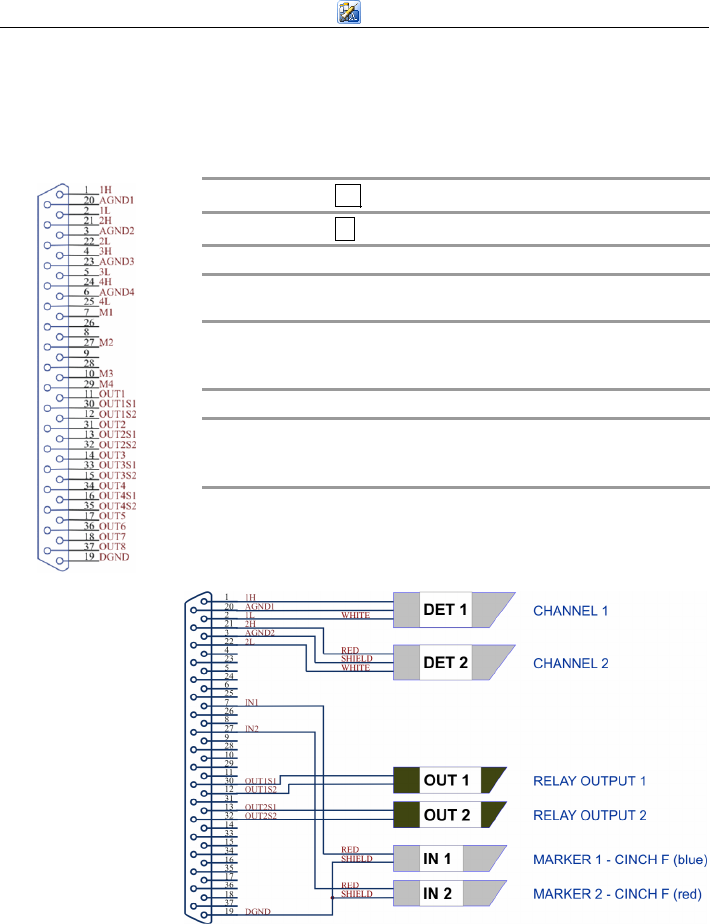
5.1 Description of the INT9 card connector (Male)
Connector pins:
1H
+ Input of the 1
st
channel
1L
- Input of the 1
st
channel
AGND1 Ground of the 1
st
channel
IN1 Digital input (of the 1
st
channel). Used as an
External Start (marker) of the 1
st
channel
OUT1 1
st
Digital output
Digital outputs are controlled by Event Table,
Active Sequence and Digital Output dialog.
DGND Ground of the digital inputs and outputs.
OUT1S1,
OUT1S2
Digital outputs - 1
st
relay contact.
Contact is closed when output is at a LOW
level.
Fig. 14. Standard INT7-compatible cable for two
detectors