


Clarity - INT9 A/D converter Using the INT9 card
19
Down
The station reacts to changes in voltage in
the relevant controlling input from high
(> 3V) to low (< 0.7 V), or to contacts closed
in the relay.
Up
The station reacts to changes in voltage in
the relevant controlling input from low
(< 0.7 V) to high (> 3V), or to contacts
opened in the relay.
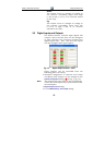
3.3 Digital Inputs and Outputs
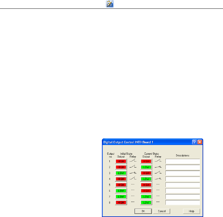
The INT9 converter contains eight digital TTL
outputs, where the first four are also designed
as relay contacts. The converter contains four
digital inputs IN1 - IN4. The first two inputs
are also equipped with optocouplers.
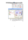
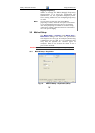
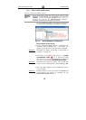
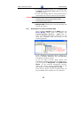
Fig. 12. Digital Output Control – INT9
These outputs can be controlled from the
following places in Clarity:
• Standard assignment of external start Input
and Ready OUT Output can be changed in the
System Configuration
dialog ( in Fig. 4, pg. 10).
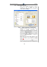
Note: The assigned input and output is then automatically
used in the Active Sequence for synchronization with
the autosampler.
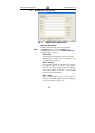
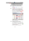
• Digital Output Control dialog.
• In the
Method Setup – Event Table dialog.