


AXIS A8004-VE Network Video Door Station
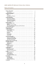
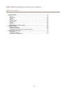
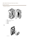
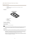
Hardware Overview
Power Connector
2-pin terminal block for power input. Use a Safety Extra Low Voltage (SELV) compliant limited power source (LPS) with either a rated
output power limited to ≤100 W or a rated output current limited to ≤5 A.
Audio Connector
2-pin terminal block for line out.
Important
External radio transmitters may interfere with the product’s microphone signal. To avoid this, install a snap ferrite (Würth,
article number 74271733) on the line out cable. The line out cable shall pass through the snap ferrite twice.
SD Card Slot
NONO
NO
TICETICE
TICE
• Risk of damage to SD card. Do not use sharp tools or excessive force when inserting or removing the SD card.
• Risk of data loss. To prevent data corruption, the SD card should be unmounted before removal. To unmount, go to Setup >
System Options > Storage > SD Card and click Unmount.
This product supports microSD/microSDHC/microSDXC card (not included).
For SD card recommendations, see www.axis.com
Control Button
For location of the control button, see Hardware Overview on page 7 .
The control button is used for:
• Enabling the Focus Assistant. Press and very quickly release the Control button.
• Resetting the product to factory default settings. See page 67.
• Connecting to an AXIS Video Hosting System service. See page 59. To connect, press and hold the button for about 3
seconds until the Status LED ashes green.
• Connecting to AXIS Internet Dynamic DNS Service. See page 59. To connect, press and hold the button for about 3 seconds.
Call Button
For location of the control button, see Hardware Overview on page 7 .
The call button is used by visitors to call users of the Axis product and its connected devices.
The built-in light around the call button can be used to light up the faces of visitors and its intensity can be controlled on the live
view page. For more information, see Light Buttons on page 38 and Controls on the Live View Page on page 13.
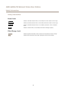
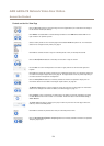
LED Indicators
Note
• The Status LED can be congured to be unlit during normal operation. To congure, go to Setup > System Options > Ports
& Devices > LED. See the online help for more information.
• The Status LED can be congured to ash while an event is active.
• The Status LED can be congured to ash for identifying the unit. Go to Setup > System Options > Maintenance .
9