


AXIS A8004-VE Network Video Door Station
Technical Specifications
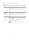
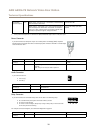
Digital input – Connect to pin 1 to activate, or leave oating
(unconnected) to deactivate.
0 to max 40 V DCCongurable
(Input or Output)
3–6
Digital output – Connected to pin 1 when activated, oating
(unconnected) when deactivated. If used with an inductive
load, e.g. a relay, a diode must be connected in parallel with
the load, for protection against voltage transients.
0 to max 40 V DC, open drain,
100 mA
1. When powered through Power over Ethernet IEEE 802.3af/802.3at Type 1 Class 3.
2. When powered through Power over Ethernet Plus (PoE+) IEEE 802.3at Type 2 Class 4 or DC power input.
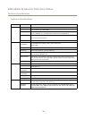
Power Connector
2-pin terminal block for DC power input. Use a Safety Extra Low Voltage (SELV) compliant
limited power source (LPS) with either a rated output power limited to ≤100 W or a rated output
current limited to ≤5 A.
Function Pin Notes
Specications
0 V DC (-)
1
0 V DC
DC input
2
For powering controller when not using Power over
Ethernet.
Note: This pin can only be used as power in.
10–28 V DC, max 26 W
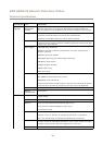
Audio Connector
2-pin terminal block for:
• Line out (+)
• 0 V DC (-)
Function Pin Notes
Line out (+)
1
Line audio out
0 V DC (-)
2
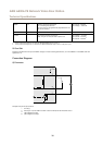
Relay Connector
6-pin terminal block for solid state relays that can be used in the following ways:
• As a standard relay that opens and closes auxiliary circuits.
• To control a lock directly.
• To control a lock through a safety relay. Using a safety relay on the secure side
of the door prevents hotwiring.
For example connection diagrams, see Connection Diagrams on page 76.
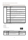
Function Pin Notes
Specications
0 V DC (-)
1
0 V DC
75