


Assembly-Level Service
Theory of Operation
2-17
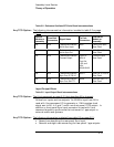
The slot/module interconnect diagram on page 3-28 is changed:
The J3 Low Current Steering Logic connector does not have +5 VDC,
POWER FAIL, or BAT VALID signals present.
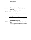
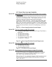
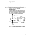
48V Subpanel Assembly
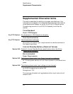
The schematic diagram in figure 2-1 below illustrates the wiring of
the 48V Subpanel Assembly. This assembly steers dc input power,
and provides fuse protection for the external 48V external dc input
power. The output of this circuit at P1 is routed to the input of the
External DC Input Filter Block (J1) illustrated at the top-left comer of
figure 3-3. in the 5071A Assembly-Level Service manual.
Figure 2-1. DC Input 1 and 2 Power Steering Schematic (48V Subpanel
Assembly, part number 05071-60277)
Option 048:
I
npu
t
2
C
h
ass
i
s
G
r
ound
+
+
-
-
I
npu
t
1
+
-
CR
4
CR
3
Grn/Yel
Blk
Grn/Yel
Red Red
P1
To A1
MP3
Solder Lug
MP2
3 Position Solder
Terminal strip
MP3
Rear Panel
DC Fuse Holder
F2 2.5A DC Fuse
MP1
Rear Panel
DC Power
5 Position screw
Terminal strip
CR
2
CR
1