


Assembly-Level Service
Theory of Operation
2-13
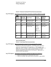
Table 3-2. Reference Oscillator/RF-Chain Block Interconnections
The following interconnection information is added to table 3-2 on page
3-16:
Source
Module or
Assembly
From Path
Connectors
Signal Name
To Path
Connectors
Destination
Module or
Assembly
A9 N/A Telecommunications
8 kHz Sync Input
A9J7 8 kHz Sync Input,
Rear Panel
A9 N/A Telecommunications
8 kHz Sync Out
A9J8 8 kHz Sync Out,
Rear Panel
A9 N/A Telecommunications
Framed Output
Opt 27n:
A9J10
Opt 104,
105, and
22n:
A9J9-A9J10
Framed Output,
Rear Panel
A9 N/A Telecommunications
Sync Out, G.703/10
A9J11 Sync Out, G.703/10
Rear Panel
A9 N/A Telecommunications
Sync Out, 50Ω TTL
A9J6
Sync out 50Ω TTL,
Rear Panel
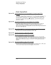
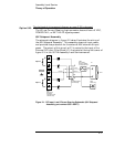
Input/Output Block
Table 3-5. Input/Output Block Interconnections
The third paragraph on page 3-21 that describes A8 is changed:
A8 has four inputs and two outputs. An 80 MHz input from A9 is
used with I-bus command I/O to generate: a. 1-MHz system clock
signal sent to A2, 4, 6, and 7, and b. one front-panel 1 PPS output. In
addition, a front-panel Sync input connector is used with I-bus
command signals to synchronize the instrument’s 1-pps output to
external events and systems.
The following information is deleted from table 3-5 on page 3-21:
• Second row describing the rear-panel Sync Input,
• Seventh and eight rows concerning the rear-panel 1 pps outputs.
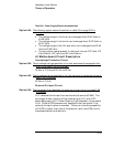
Any TCO Option:
Any TCO Option:
Any TCO Option: