


Assembly-Level Service
Theory of Operation
2-15
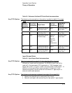
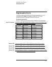
Table 3-6. Power Supply Block Interconnections
The following signal name information in table 3-6 on page 3-23 is
changed:
• The voltage range in the third row is changed from 22-42 Volts to
40-58 Volts.
• The voltage range in the fourth row is changed from 32-38 Volts to
45-51 Volts.
• The voltage range in the fifth and sixth row is changed from 22-42
Volts to 40-58 Volts.
• The only signal names present in the tenth row are: DC Valid, DC
Valid Return, AC Valid, and AC Valid Return.
A1 Motherboard Circuit Description
Overvoltage Protection Circuit
The dc voltage ratings specified in the last sentences of paragraphs four
and five on page 3-24 are changed:
56 Vdc is 72 Vdc and 50 Vdc is 65 Vdc.
The dc voltage rating specified in the last sentence of paragraph three on
page 3-25 is changed:
56 Vdc is 72 Vdc.
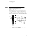
External Dc Input Circuit
The paragraph that describes the external dc input circuit on page 3-25
is changed:
A1J1 receives the dc input from an external dc source (40-58V). The
dc voltage is then routed to a filter consisting of A1L1 and A1C2
before being sent to A11 Power Steering Logic Assembly via connector
A1J4. Diode A1CR2 prevents any damage to the instrument if the
external dc-input source is reversed. The current handling capability
of A1CR2 is higher than that of the external input fuse (2.5A) so the
fuse blows before the diode fails.
Option 048:
Option 048:
Option 048:
Option 048: