


Operating and Programming
Installation
1-12
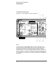
Preparing the RP 5071-A For External-Dc Operation
Delete the existing procedure and use the following procedure
1. Connect the positive (+) terminal of the 40 to 58 Vdc power to the
+ screw terminal of INPUT 1 on the rear-panel 5-terminal barrier
strip.
2. Connect the minus (–) terminal of the 40 to 58 Vdc power to the –
screw terminal of INPUT 1 on the rear-panel 5-terminal barrier
strip.
3. Connect the system or power source ground terminal to the 3rd
(center) screw terminal of the rear-panel barrier strip labeled
chassis GND.
4. Check your connections for correct polarity, voltage range, and
tightness before you turn the dc power on.
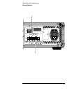
5. If a second 48 Vdc power source will be used, repeat steps 1
through 4 with INPUT 2 of the rear-panel barrier strip. (INPUT 2
will be an alternate power source if INPUT 1 should fail, be
disconnected, or sag below the voltage of INPUT 2.)
6. Connect external ac power to the rear-panel ac input connector.
7. Remove dc power from INPUT 1 (and INPUT 2 if connected) on the
rear-panel barrier strip. Observe the front panel, the status
message should read: source AC.
8. Reapply dc power to the instrument; the front-panel status
message reads: source DC.
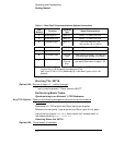
Replacing the External Dc Input Power Fuse
Step 3 of the procedure is changed:
3. Insert the replacement fuse (2.5 A, 250-volt rating, part number
2110-0952).
Internal Standby Battery Maintenance
All procedures are deleted.
Long-Term Storage
The last parenthetical sentence of the last paragraph referencing the
internal-standby battery is deleted-
Option 048:
Option 048:
Option 048:
Option 048: