


Assembly-Level Service
Service
2-9
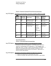
A9 Diagnostic Tree (A/M Subsection 4)
3.4.5.0 A9 Mon Signal Test
This procedure is deleted.
3.4.6.0 A9 J4 80-MHz Signal Test
This procedure is deleted.
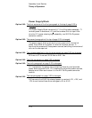
The following procedure is added:
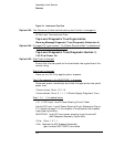
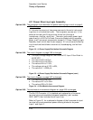
4.4.4.1 A9-to-Chassis TCO Option signal Interconnect Test
If one or more of the four rear-panel telecommunications outputs are
absent or operating out of specification, use the following procedure to
isolate the fault.
1 Remove instrument power.
2 Carefully remove the five (or six for a differential framed output)
telecomm signal SMB cable connectors (Note their locations first.)
from J6, J7, J8, (J9 - used only for options 104, 105, 220, 221, and
222), J10, and J11 on A9.
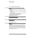
3 Verify continuity and rule out short-to-ground for all five cables and
their corresponding rear-panel input and outputs.
4 Reconnect the verified cables and connectors.
QUESTION: Are any of the five SMB-to-BNC cable assemblies open
or shorted?
If Yes: Replace the cable assembly as required and retest.
If No: Reapply instrument power, retest A9 TCO input/outputs, and
replace A9 if any TCO signal output fault persists.
Any TCO Option:
Any TCO Option:
Any TCO Option: