


Assembly-Level Service
Theory of Operation
2-12
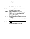
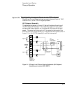
Figure 3-2. 5071 A Overall Block Diagram (Continued)
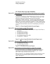
The A8 1 PPS Assembly has the following input/output changes:
Input B is deleted.
Both rear-panel 1 PPS outputs are deleted.
The Power-Supply Block has the following changes:
The DC Power input voltage is changed from 22-42V to 40-58V
The B1 24V Battery and A11 Battery Charger are deleted.
Instrument Control Block
Operating Firmware: Warning Mode
The first sentence of the Warning Mode description at the top of page
3-14 is changed:
The warning mode occurs when the health monitor detects a possible
problem.
Reference Oscillator/RF-Chain Block
The third paragraph on page 3-15 that describes A9 has an additional
sentence:
In addition, all telecommunications options sync input and outputs
are routed to and synthesized within the A9 module.
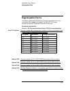
Any TCO Option:
Option 048:
Option 048:
Any TCO Option: