


Assembly-Level Service
Theory of Operation
2-16
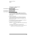
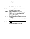
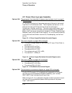
A11 Power Steering Logic Assembly
The paragraph that describes the power-steering logic circuit on page 3-
25 is changed:
A11 directs the outputs of two power sources to the main instrument
input bus in a hierarchical order. The two power sources are: 1) the
external dc input and 2) the dc from the ac line (through a
transformer, rectifier, and filter). The main instrument power input
goes directly to A12 Dc-Dc Power Converter Module which supplies
power to all instrument components (except A11 Power Steering Logic
Assembly itself, which has its own supply). All circuits are divided up
into three functional blocks: external dc, housekeeping, and dc from
ac line.
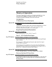
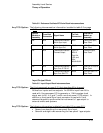
Figure 3-3. A1 Power Supply/Distribution Schematic Diagram
The circuit diagram on page 3-26 is changed:
• The input voltage range for the External DC Input Filter Block is
40-58 VDC,
• The value of C2 is 470 µf,
• The value of C4 is 4700 µf ,
• The value of R4 is 17.8 Ω,
• The voltage rating of VR1 is 68V,
• The value of L1 is 235 µH.
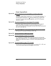
Figure 3-3. A1 Power Supply/Distribution Schematic Diagram (cont.)
The circuit diagram on page 3-27 is changed:
• The value of C3 is 470 µf,
• The value of R7 is 31.6 kΩ.
• The value of R8 is 31.6 kΩ.
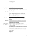
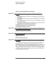
Figure 3-4. A1 Slot/Module Interconnect Diagram
The slot/module interconnect diagram on -page 3-28 is changed.
The Ext DC Connector (J1) is deleted and replaced by a five-screw
terminal strip and associated subpanel assembly ( part number
05071-60277) that includes the dc input fuse.
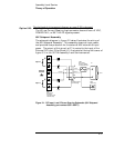
Refer to Figure 2-1 for a schematic diagram of the five-screw dc input
terminal strip and associated power steering diodes for dc power
input 1 and input 2.
Option 048:
Option 048:
Option 048:
Option 048: