


13
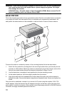
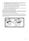
5. Before inserting the scanner in the sleeve, attach the cable from the previously mounted
antenna. Attach the DC Power leads. RED goes to a positive (+) connection on your fuse
block while BLACK connects to the vehicles chassis ground (-).
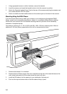
6. Connect the ORANGE lead to one side of the headlamp switch so that when you activate
the headlights, the scanners LCD display changes intensity. Be sure all the connections are
routed away from any potentially pinching or slicing sheet metal.
7. Slowly slide the scanner into the sleeve until it locks in place.
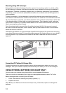
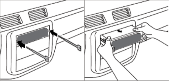
8. To remove the unit, fully insert the removal keys into each slot on the left and right edges of
the front panel. Carefully slide the radio from the sleeve.
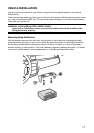
Removing the Scanner from the DIN-E Sleeve
If you plan to connect other devices or wires to the radio, such as a GPS unit, at a later time, you
should plan to remove the scanner from the DIN-E sleeve. This is easily done using the provided
Removal Keys that come with the optional DIN-E sleeve.
Refer to the illustration that follows, showing the Removal Keys.
Fully insert both Removal Keys into the slots on the left and the right edges of the radios dress
panel. You cannot remove the radio with only one key. Press in fully, and do not twist the keys.
The radio will unlock from the sleeve making withdrawal from the sleeve possible. Store the keys
in a safe place for future use.