Chapter 3 - Design of Party-Line Intercom Systems 35
Modes
The following modes exist in intercom systems:
M2) Two-Wire.
M4) Four-Wire.
The following sub-modes are considered for two-wire and four-wire:
M2F) Two-Wire, Full Duplex.
M2H) Two-Wire, Simplex.
M4F) Four-Wire, Full Duplex.
M4H) Four-Wire, Simplex.
Level Problems
One problem in interfacing from two-wire to two-wire is caused by the 2 wire systems’
use of 2 to 4 wire hybrids. Interfacing requires conversion from two-wire to four-wire
twice to allow level adjustments to and from systems. The quality of the two-wire to four-
wire hybrid limits the amount of make-up gain available to match levels in one system or
the other.
Another problem with interfacing is that level adjustment is difficult when interfacing
from a limiter controlled system, such as the TW Intercom System, to a non-limiter
controlled system, such as some two or four wire systems. The reason for the difficulty is
that the perceived loudness is greater on the TW System and much less on the non-limiter
controlled system. This difference can be improved or eliminated depending on two
limiting factors: 1) the headroom of the electronics involved, and 2) the quality of any two-
wire to four-wire hybrids in the path. Interfacing from two-wire to two-wire systems is the
most difficult. Interfacing from two-wire to four-wire is easier, and interfacing from four-
wire to four-wire is the easiest. The problem in two-wire / two-wire interfacing is getting
the levels right and preventing oscillations.
The level of the TW and 800 Series conference intercom systems ranges from -10 dBu to
0 dBu, with an average value of - 6 dBu, and is limiter controlled.
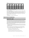
Some other systems are listed in Table 3-2. The objective is to convert the modes and to
adjust the levels.
Signal / Data Conversion
Call Light
Some intercom systems use a “Call Light” signal to illuminate lights in individual stations.
This signal may be a 20 kHz tone, a DC level, or a digital logic level. An interfacing
device may handle the method conversion to carry the call light signal.
Data
Other systems have data flow via various methods including: contact closure, logic level,
RS485 bus, RS422 bus, and RS232 bus. The handling of the RSxxx signals is done best on
a case-by-case basis. At this point, system-to-system communications is done via RS232
communications by wire, fiber optic, or telephone lines via modem. Some system-to-
system communication is accomplished through user specified hardware imbedded in
special products.
Some Master Stations have an RS232/485 connection that allows control of the station
over a terminal or another computer.


