


A Comparison of Relative System Sizes - - - - - - - - - - - - - - - - - - - - - - - - - - - - - - -70
Separate Studios, Separate Intercom - - - - - - - - - - - - - - - - - - - - - - - - - - - - - - - - - -71
Fixed Trunking - - - - - - - - - - - - - - - - - - - - - - - - - - - - - - - - - - - - - - - - - - - - - - - -72
Intelligent Trunking - - - - - - - - - - - - - - - - - - - - - - - - - - - - - - - - - - - - - - - - - - - - -74
Cascaded Trunking - - - - - - - - - - - - - - - - - - - - - - - - - - - - - - - - - - - - - - - - - - - - -76
TW and Matrix Signal Flows - - - - - - - - - - - - - - - - - - - - - - - - - - - - - - - - - - - - - -78
Wireless Intercom Interfaced to Matrix Intercom - - - - - - - - - - - - - - - - - - - - - - - - -79
GPI/O Implemented PTT (Push-To-Talk) - - - - - - - - - - - - - - - - - - - - - - - - - - - - - -80
TW to Matrix Interface 81
ADAM™ and ADAM™ CS Basic Components - - - - - - - - - - - - - - - - - - - - - - - - -82
Matrix Intercom Remote Control - - - - - - - - - - - - - - - - - - - - - - - - - - - - - - - - - - - 83
The first beltpack based wireless intercom system. - - - - - - - - - - - - - - - - - - - - - - - -87
An example of a modern day wireless intercom system. - - - - - - - - - - - - - - - - - - - -88
The RadioCom™ BTR-800 System is an outstanding example of the
next generation of wireless intercom systems. - - - - - - - - - - - - - - - - - - - - - - - - - - -89
NTSC channel configuration. - - - - - - - - - - - - - - - - - - - - - - - - - - - - - - - - - - - - - -90
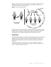
The E an H fields exist in two separate planes, 90° apart from each other. - - - - - - - -96
An example of wireless transmission and reception. - - - - - - - - - - - - - - - - - - - - - - -97
An example of electromagnetic waves being radiated. - - - - - - - - - - - - - - - - - - - - - 97
An example of reflected RF waves.- - - - - - - - - - - - - - - - - - - - - - - - - - - - - - - - - - -98
The orientation of the radiator (antenna) determines the polarization,
and therefore, the orientation of the E and H fields. - - - - - - - - - - - - - - - - - - - - - - -99
Waves that are in phase combine to form a larger wave. - - - - - - - - - - - - - - - - - - - -99
Waves that are out of phase cancel each other. - - - - - - - - - - - - - - - - - - - - - - - - - - -99
An example of combining waves that are not 180° out of phase. - - - - - - - - - - - - - - 100
An example of multipath in its most basic form. - - - - - - - - - - - - - - - - - - - - - - - - - 100
Transmitter block diagram. - - - - - - - - - - - - - - - - - - - - - - - - - - - - - - - - - - - - - - - 102
Receiver block diagram. - - - - - - - - - - - - - - - - - - - - - - - - - - - - - - - - - - - - - - - - - 103
Good linearity is a must for faithful signal reproduction. - - - - - - - - - - - - - - - - - - - 104
A comparison of the radiation patterns for an Isotropic Radiator
(theoretical) vs. a Dipole (practical). - - - - - - - - - - - - - - - - - - - - - - - - - - - - - - - - 105
An example of a Yagi antenna. - - - - - - - - - - - - - - - - - - - - - - - - - - - - - - - - - - - - 107
Telex®’s ALP-450 is an example of a Log Periodic antenna. - - - - - - - - - - - - - - - - 107
The typical parts of coaxial cable. - - - - - - - - - - - - - - - - - - - - - - - - - - - - - - - - - - 109
Wiring differences between larger conference and point-to-point styles. - - - - - - - - - 114
Figure 3. Block diagram of a medium sized intercom system using two-wire.
The forms of communications depicted here are six conference lines and eight
IFB circuits. - - - - - - - - - - - - - - - - - - - - - - - - - - - - - - - - - - - - - - - - - - - - - - - - 119
Block diagram of a medium sized intercom system using the Zeus™
four-wire matrix. The forms of communications depicted have
increased to include point-to-point and ISO. - - - - - - - - - - - - - - - - - - - - - - - - - - - 121
Figure 5. Block diagram of a large size intercom system using a twin
ADAM™ configured as a 200x200 matrix. - - - - - - - - - - - - - - - - - - - - - - - - - - - 123