


124 Handbook of Intercom Systems Engineering
large design effortless. Apparent in our sample system is the ADAM here is a storehouse
for 10 separate intercom systems! These internal intercom systems are configured to work
separately or concurrently with each other. With the new automated server feature in AZ-
Edit, files can be downloaded without human intervention by the powerful new UPL (User
Programmable Language). This set of useful Boolean algebra expressions allows an
almost endless chain of events to be introduced to the system to solve any problem. In
short, the days of custom intercoms are over.
Determining the Makeup of the Intercom Matrix
First Step--Determine the Size
The matrix is composed of audio in/out ports (four-wire). These are further classified as
panel ports (6 wire) and non-panel ports (four-wire). A non-panel port is simply a regular
port without the data lines tied to the matrix leaving only the four-wire audio in and audio
out. A typical broadcast intercom system consists of Users, IFB Circuits, Cameras, and
Miscellaneous ports (to include static Party-Line systems, 2-way radios, telephones, etc.).
The first step is to determine the size of the central matrix by counting everything that is
attached it. We will use our large sample for this exercise.
Users
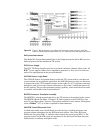
The users of the matrix are operators with keypanels. Going down the list of stations
(derived from a source-destination table, block diagram, or position list), we count them
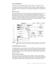
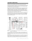
one by one. In figure 5, we have 10 keypanels x 6 large control rooms plus 1 keypanel x 4
small control rooms. Thus, in this example, we have a total 64 users. The 64 users narrow
our deciding matrix down to either an ADAM or ADAM
™
-CS (barely) depending on
subsequent port counts. A Zeus (24x24) would definitely be too small.
IFB Circuits
The next port count we need to add is the number of IFB circuits. All RTS
™
matrices have
the unique ability to use a port delegated for IFB in a split fashion. What this means is a
port counted for IFB automatically yields an input port for the program feed from the
audio console. Therefore, program sources do not typically become a factor in the count
unless there are more of them than IFB circuits. The situation is rare, though.
The IFB circuit, used in virtually all television facilities, is usually a one direction audio
cue to on-air talent. The signal interrupts a predefined audio source, such as program
audio, to inject a directive from the director, producer or audio. In its simplest form, IFB
uses an earpiece, an external headphone box (to permit the talent to control the audio
foldback level), a program source and a control station. A common IFB application is the
live TV newscast where a director wishes to advise the talent a cut-in is starting.
Since all routing of the programs to IFBs is performed outside the matrix in our example,
no large matrix assignment panel, such as the LCP102 (64x64 switcher) or PAP950-50
(50x50 switcher), is required. Unlike the PAP951 and PAP952, these panels sometimes
find use in larger systems because of their ability to switch to any part of the matrix and
thus, not fixed to any section.
With the influx of ENG vehicles, many of today’s IFB circuits are telephone dial-in. These
particular circuits are sometimes left out of the count for various reasons. Including all IFB
circuits not only insures correct matrix size, but also helps specify ancillary equipment
such as the program assignment panel as described above.