


106 Handbook of Intercom Systems Engineering
squeezed the balloon’s center with your hands, a corresponding bulge would appear on
either end. The balloon is not any larger or smaller than it was, it has only changed shape.
This is how a real world antenna works. When energy is focused in one direction, it must
always be at the expense of energy going in another direction.
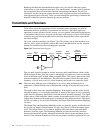
The most basic form of real world antenna is the dipole. The dipole has 2.15 dBi of
antenna gain over an isotropic radiator. That means there is 2.15 dB more signal in the
direction that the energy is focused than there would be if the antenna were an isotropic
radiator. Antenna gain is specified in one of two ways: dBi or dBd. It is very important to
know which specification is being used when comparing antennas. dBi, as stated above, is
referenced to the uniform radiation of an isotropic radiator. dBd, on the other hand, is
referenced to a dipole. Most antenna manufacturers like the dBi spec because the number
is bigger, but since there is no real world antenna that represents the 0 dB mark, many
engineers prefer dBd. In reality, either specification is fine as long as you are comparing
apples to apples. In the remainder of this book all antenna gain references will be in dBd,
referenced to a dipole, unless otherwise specified.
Important:
If you need to convert from dBi to dBd, simply subtract 2.15 dB from the dBi number. If
you need to convert from dBd to dBi, simply add 2.15 dB to the dBd number.
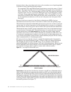
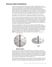
There are two basic groups of antennas, omni directional and directional antennas. Omni
directional antennas are generally low gain antennas used in the center of operational
areas. Because the RF energy in omni directional antennas is in 360° and not in one
specific direction, the antenna gain must always be low. The isotropic radiator and dipole
antennas are both examples of omni directional antennas. Normally, omni directional
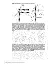
antennas will be found with antenna gain less that 5 dBd. Gain in omni directional
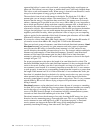
antennas is achieved by flattening the vertical angle of the pattern as shown in the dipole
example in Figure 7.13.
For proper propagation to take place, the length of an omni directional in critical. The
theoretical minimum length for an omni directional antenna is ½ the wavelength of the RF
carrier to be served. In many cases this ½ wave length is too long to be practical so a ¼
wave antenna is used instead. It is extremely important to note that for a ¼ wave antenna
to work properly, it must have a corresponding ground plane that is equal to or greater than
the length of the antenna itself. It is for this reason that a ¼ wave antenna that works just
fine when it is attached directly to the back of a wireless receiver has very poor coverage
when operated at the end of a length of coaxial cable. The cable does not provide the
necessary ground plane for proper ¼ operation as the receiver does. This is a very common
mistake made by RF novices who are trying to improve RF performance and end up
killing it instead!
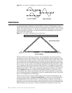
Directional antennas, on the other hand, seek to focus the area of coverage to something
less than 360° to form a flashlight like coverage pattern. Directional antennas are normally
used on the edge of a coverage area. They can have very high antenna gain factors in
excess of 20 dBd. Normally though, in conventional wireless communications systems,
size and cost limit directional antenna gain to less than 12 dBd.
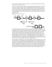
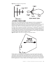
Directional antennas have the advantage of not only focusing the RF energy in a given
direction, but also attenuating energy from undesired areas. This is very important for
receive antennas in areas with high levels of RF. If positioned properly, a directional
receive antenna can increase the desired RF energy while attenuating unwanted,
potentially interfering RF energy from other areas. See Figure 7.14.