


Chapter 7 - Design of Wireless Intercom Systems 105
Antenna & Cable Considerations
Antennas and cables (transmission lines) are one of the least thought about aspects of a
wireless system among RF novices. Good quality antennas and cables, however, are some
of the most important aspects to establishing and maintaining a quality RF link. In
addition, because antennas and cables are more easily changed and in general are less
expensive than other system components, they can be a “quick fix” for many RF problems
found in common wireless communications systems. In this section, we cover some of the
more common types of antennas and the operating characteristics of each. In addition, we
take a look at coaxial cable and what is required when selecting cable for your system.
To adequately look at and evaluate the strengths and weaknesses of some common
antenna types, we first must have a very general knowledge of antenna theory. Antenna
theory is a course of study unto itself and we will not even scratch the surface in this brief
section, but it should be enough to understand some basic principles. To start, let’s ask the
question, “What is an antenna?” To answer that question we must look at what an antenna
does. In a transmitter, the antenna takes electrical energy and allows it to be propagated
out into the electromagnetic spectrum. In a receiver the antenna “gathers” the RF signal
and converts it back into electrical voltages and currents. In either case, the antenna acts as
a transducer to change the form of the RF energy.
All real world antennas have a pattern or specific shape with which the RF energy is
released or captured. There is no such thing as an antenna that sends energy out equally in
all directions. The primary reason for this is that you have to get the signal to the antenna
via a transmission line and that line must be connected to the antenna some how. That
connection will always cause a disruption or altering of RF propagation in some direction.
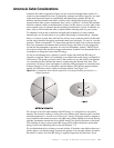
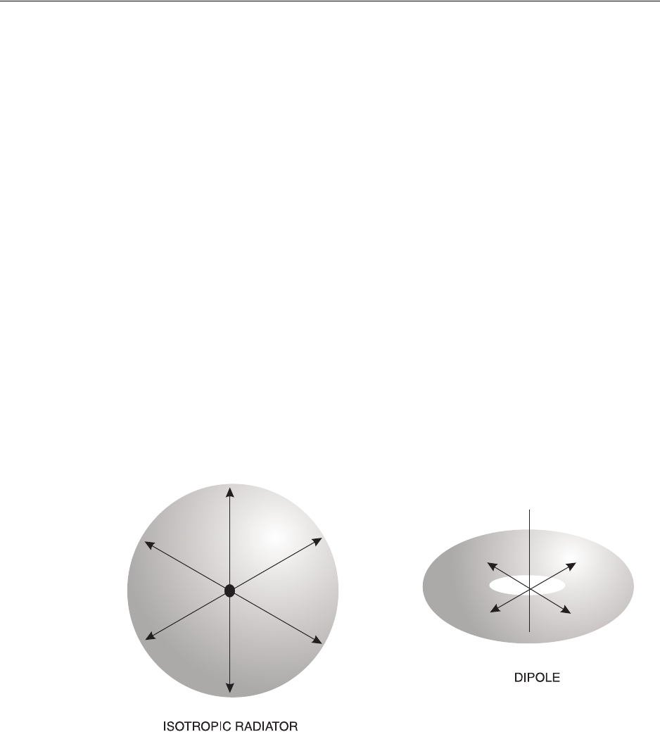
In theory though, it is nice to talk about a perfect antenna. This perfect antenna radiates
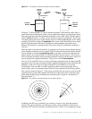
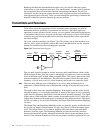
equally in all directions and is called an isotropic radiator. See Figure 7.13.
Figure 7.13
A comparison of the radiation patterns for an Isotropic Radiator (theoretical) vs. a
Dipole (practical).
We can look at how all other antennas emit RF energy as a comparison to our perfect
antenna. The isotropic radiator is said to have zero antenna gain. Antenna gain is an often
misunderstood term, so we will cover it here. Let’s start by saying that a passive antenna is
not an amplifier and cannot increase to total RF energy being emitted or received. Having
said that, an antenna can and does focus the RF energy in a specific direction or directions.
This focusing of energy causes greater RF energy levels in those directions and weaker
energy levels in the remaining areas as shown in Figure 7.13.
We can think about this by looking at a water balloon. If we had a water balloon that was a
perfect sphere, it would accurately represent the pattern of an isotropic radiator located in
the balloon’s center. All of the RF energy is equally dispersed in all directions. If you