


98 Handbook of Intercom Systems Engineering
because it shows why a wave that travels twice as far as another wave of equal magnitude
is not half as strong. Take the following example:
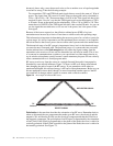
Two transmitters TXA and TXB both emit signals that are exactly the same at 1 Watt of
power. The signal from TXA travels 10 units. Power at that point can be calculated by
1/10
2
x 1W or 0.01 x 1W. That means there is 0.01W of the TXA signal left after it has
traveled 10 units. Now let’s say that the TXB signal travels twice the distance of TXA
or 20 units. Power at that point can be calculated by 1/20
2
x 1W or 0.0025 x 1W. That
means there is 0.0025W of the TXB signal left after it has traveled 20 units. As you can
see, the signal that traveled twice as far was not ½ the power, but ¼ the power of the
first signal.
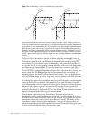
Because of the inverse square law, the effective radiated power (ERP) of a given
transmitter must increase by a factor of four times to achieve twice the operating range.
This information is important in determining the necessary power for a wireless system for
a given range. It is always important to use the minimum power necessary to accomplish
the task at hand so that excess power does not affect other systems and cause undue harm.
The theoretical range of an RF system is important to know, but it is the functional range
you must be more concerned with. The functional range of a system takes into account a
certain cushion factor called fade margin that will ensure the signal coming from the
transmitter to the receiver will not only be detectable, but will also be usable. This is less
of a concern in communications systems as you can tolerate less fade margin than in an
on-air wireless microphone system, because a small momentary dropout will not critically
affect communications as it would program audio.
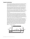
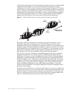
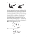
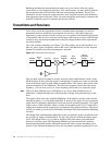
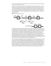
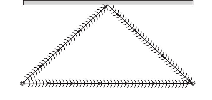
RF waves travel away from the source in a straight line until that path is interrupted or
disturbed by some outside influence. Figure 7.4 shows an RF wave being reflected and
thus changing the path of some of the RF energy. If you remember earlier when we
mentioned multipath, this reflected energy is the cause of that phenomenon. Before we can
discuss multipath in more detail, though, we must learn about another aspect of the RF
wave and how it changes when it comes in contact with a reflective surface.
Figure 7.4
An example of reflected RF waves.
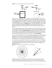
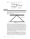
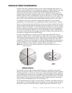
Polarization is the term that describes the orientation of an RF wave. Remember back to
when we discussed the two components that make up an RF wave, the electrical and the
magnetic. We said that the E field was the electrical component and that the H field was
the magnetic component. The polarization of an RF signal is determined by the orientation
of the E field. If the E field is perpendicular to the plane of the Earth, the wave is said to be
vertically polarized. If the E field is parallel to the plane of the Earth, the wave is said to be
horizontally polarized. See Figure 7.5.
REFLECTED SIGNAL
TX
Antenna
DIRECT SIGNAL
RX
Antenna