


12 Handbook of Intercom Systems Engineering
Alternately, newer units have two talk buttons, two volume controls, and two status
indicators to tell which talk button is engaged. Examples: RTS
™
BP325, BP351, Clear-
Com
®
RS-522-TW, or Audiocom
®
IC-2B.
Speaker User Station Functional Description
A typical speaker station can function with either a headset or a speaker/microphone. A
power amplifier, a speaker, and a speaker on/off switch are added to the electronics of a
belt pack. In addition, a nulling adjustment is easily accessible. The nulling adjustment
allows for full duplex operation without unwanted feedback. Also added is a connection or
jack for either a panel microphone (rack mount stations) or a push to talk microphone (for
desk mount or portable speaker stations).
Master Stations
The Master Station allows a user to access multiple channels. This allows different crews
to be monitored, cued or updated. If the master station is used for training, again, different
crews may be monitored and guided. These master stations have extra features for special
tasks such as IFB (Interrupted FeedBack) or SA (Stage Announce), relay closures, “hot”
microphones, and microphone kill. Master stations can send and receive call light signals
on any channel. Two examples of the Master station are Clear-Com
®
Model 912 (12
channel) and RTS
™
Model 803 (12 channel). Audiocom’s master station is modular and
can be as few as 2 channels or as many as 22 channels. Master stations allow simultaneous
monitoring of any channel, any combination of channels, or all the channels. They can call
or “mic kill” on any given channel. In addition, some master stations can monitor a
program source.
Some Technical Notes About The Stations Above
The stations mentioned above generally are designed for the dynamic microphones in the
headsets to have an impedance of about 150 to 500 ohms. The speaker station panel
electret microphones are designed to have an impedance of 1000 to 2000 ohms and require
1 to 5 volts excitation. And, the push-to-talk microphones have around 500 ohms. This
means the actual input impedance of the station microphone preamplifier will range from
470 ohms to 5000 ohms. The low impedance of 470 ohms minimizes the crosstalk in the
headset cord. The headphone impedances expected range from 50 ohms to 1000 ohms.
The 50 ohm headphones along with suitable headphone amplifiers provide enough SPL
(Sound Pressure Level) to overcome the interference from loud concerts and sports events.
The headphones also need to have an acoustic isolation of 20dB or more to protect the
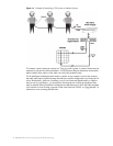
user. These stations generally have a bridging impedance across the intercom line of
10,000 to 15,000 ohms. A bridging impedance of 10,000 ohms assures that up to 50
stations can be plugged into the systems and the level drop will only be 6dB. The level
drop of 6dB corresponds to the level drop when an extension telephone is picked up on an
existing conversation-noticeable but the telephone is still usable.
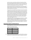
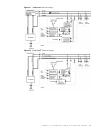
Wiring Notes
1 Clear-Com
®
and Audiocom
®
two channel stations have 6 pin XLR connectors to
connect to the intercom line. Clear-Com also offers the Clear-Com
®
RS-522-TW,
which has two channels on a 3 pin XLR.
2 Clear-Com
®
and Audiocom
®
systems use a female 4 or 5 pin XLR connector on their
headsets and a male 4 or 5 pin XLR connector on their user stations. However, RTS
uses a male 4 or 5 pin XLR connector on their headsets and a female 4 or 5 pin XLR
connector on their user stations.
3 In any system, pin 1 and the shell of the XLR connector should NOT be connected
together.