


102 Handbook of Intercom Systems Engineering
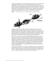
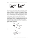
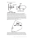
Reducing the effect that intermodulation can have on your wireless intercom system
comes down to a few important principles. First, and foremost, you must pick frequencies
that are intermod free with each other and with surrounding transmitters. Second, you
should pick wireless intercom systems that have well designed receivers and transmitters
with appropriate passive filtering. Third, you must manage the positioning of antennas and
beltpacks within the system to optimize operational potential.
Transmitters and Receivers
To be able to select the appropriate wireless communications equipment you need to
understand the basic operations of transmitters and receivers, and which aspects are
important to proper operation. In this section, we cover generic functional block diagrams
of transmitters and receivers, and point out the most critical aspects of each. While design
variations are great between manufacturers, the block diagrams that follow represent the
most basic designs.
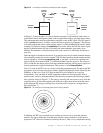
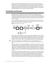
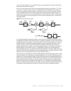
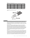
Let’s start with the transmitter (see Figure 7.10). The primary job of the transmitter is to
take in a source signal, modulate it onto an RF carrier, and then deliver it to the transmit
antenna for broadcast into the electromagnetic spectrum.
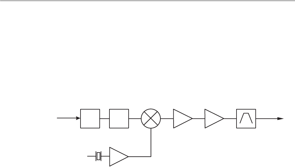
Figure 7.10
Transmitter block diagram.
First, an audio signal is brought in and any necessary audio amplification is done via the
Mic/Line Input section. Next, the signal is sent through a Compressor circuit to ensure the
levels of the input signal are held within acceptable limits. The signal is then mixed with a
reference frequency in the Modulator. This reference frequency can be the main carrier
frequency, or (as in most cases) it is a base frequency that results in a composite signal.
Note
There are many different types of Modulators, as well as, many different types of
modulation. A detailed discussion of their detailed workings is beyond the scope of this
book.
The signal is then sent to the Amplifier/Multiplier. If the signal is already on the desired
transmit frequency, it is only further amplified. If, however, the signal is only a composite
signal, then it is frequency multiplied to reach the desired operating frequency. The signal
is then sent to a Final Amplifier where it reaches its maximum power level. Usually this is
slightly more than the actual output power as measured at the output connector. The reason
for this is to make up for the losses induced by the Output Filter and Impedance Matching
circuit(s).
The Output Filter and Impedance Matching circuits are generally passive and therefore, do
not provide any means of amplification. As such, they can only reduce the output signal
levels. The Output Filter is a very narrow bandpass filter that removes any unwanted
harmonics from the signal. The Impedance Matcher provides the necessary interface
between the transmitter and the Antenna/Transmission Line to ensure maximum power
transfer. If the Antenna/Transmission Line are not properly matched, significant loss can
Mic/Line
Input
SOURCE
SIGNAL
Compressor
TO
ANTENNA
Modulator
Amplifier
Multiplier
Final
Amplifier
Filter &
Impedance
Matcher