Chapter 7 - Design of Wireless Intercom Systems 103
occur. In some situations, it is possible for this to cause damage to either the transmitter,
transmission line, and/or antenna.
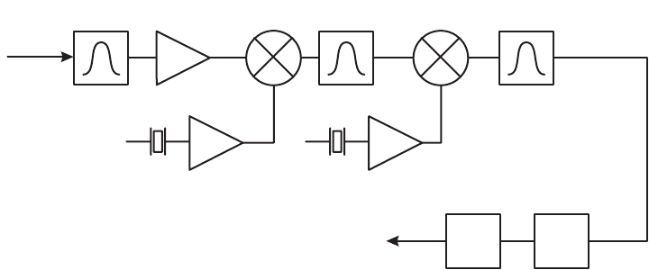
Now let’s look at the receiver and it’s primary functional aspects (see Figure 7.11). The
receiver in a wireless system is the exact compliment of the transmitter, but is usually
much more sophisticated and complex in design. Its job is to receive the signal from the
receive antenna and extract the source signal so that it matches the original exactly. In
practice, there will always be some modification or distortion of the source signal in the
course of transmission, but good quality wireless systems minimize this to a level that is
indistinguishable.
Figure 7.11
Receiver block diagram.
As in the transmitter, the antenna will be covered in the next section. The receiver starts
with the front-end filter. The front-end filter is extremely important to successful operation
in high RF level environments. The front-end filter is the first line of defense. Its job is to
limit the number of potential interfering frequencies that could affect the receiver. It is
usually a passive, linear section and it must be impedance matched to the antenna for
proper signal transfer. Linearity is the most important factor in a front end, even more so
than how tight or narrow the section is. A high degree of linearity will ensure that no
intermodulation products are generated in the front end before extraneous RF signals are
filtered out. Having a front-end that is relatively tight and that is extremely linear is critical
if the system is to work properly under worst-case RF scenarios.
The next section of the receiver is the first RF amplifier. The first RF amp’s job is to take
the extremely low level RF signal coming through from the front end and bring it up to a
usable level. The incoming RF signal at the first RF amp can vary dramatically from less
than 0.5 µV to almost the value of the transmitter output. The key for the first RF amp is
that it should be able to handle very small, as well as, relatively large incoming signals
within it’s linear region of operation. See Figure 7.12. To maintain a good linear region,
RF amps normally require a high current drain which can negatively impact battery life. A
compromise between linearity and effective battery life must be managed carefully.
Front End
Filter
FROM
ANTENNA
RF
Amplifier
TO
AUDIO PROCESSOR
Mixer
Ist IF
Filter
1st Local
Oscillator
Mixer
2nd Local
Oscillator
2nd IF
Filter
DemodulatorExpander


