


Chapter 2 - Introduction to Party-Line Intercom Systems 13
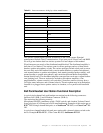
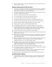
4 The pin out of the headset connectors is as follows:
Four pin XLR
Pin 1 - Microphone common
Pin 2 - Microphone “hot”
Pin 3 - Headphone common
Pin 4 - Headphone “hot”
Five pin XLR
Pin 1 - Microphone common
Pin 2 - Microphone “hot”
Pin 3 - Headphone common
Pin 4 - Left Headphone “hot”
Pin 5 - Right Headphone “hot”
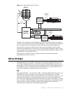
5 Since the power supply has a limited amount of XLR-3 connectors, splitter boxes are
used to expand the system. These boxes have all the connectors wired in parallel.
6 Some user stations have “loop-thru” connectors that allow “daisy chaining” stations
using a single connection to the power supply.
How Each System Works
Note
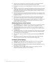
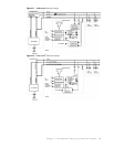
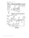
Drawings at the end of the chapter depict the systems being discussed.
First, please note that although these systems are full duplex and everybody could
theoretically talk at once, this is not at all practical or desirable. The usual operation is the
director or lead person has their microphone enabled all the time, while all other
microphones are switched off. These microphones are switched on only long enough to
supply an answer, make a request, or give data. In some cases, especially in noisy
environments, all microphones are off and only switched on as required. Because the
Party-Line concept has so many signal sources, this operational protocol is the only way
the Party-Line can be effective. And this is the reason for the system “mic kill”
(microphone turn-off) capability, for the situation where a station is unmanned but has its
microphone enabled.
These systems use voltage controlled current sources (or similar electronics) to apply a
signal to the intercom line. All the signals applied are summed and converted to a voltage
at the single termination resistor or electronic impedance. The current sources (or similar
circuits) have output impedances of 10,000 ohms or greater. The loading effect of the
station on the intercom, say in a 200 ohm terminated system is, worst case, 10,000 ohms in
parallel with 200 ohms. This results in a change of the system termination to 196 ohms, a 2
percent change. This, in turn, causes a voltage change of 2 percent or 0.175dB, an
imperceptible change. It takes 20 stations across the line to cause a 3dB change, a
perceptible but not significant change. The volume controls in the user stations easily
adjust for this change. In the “not so” worst-case situation, these systems can work with up
to 75 stations, provided enough DC power is available. The work-around in this case, in
the RTS
™
TW system, is a switch on the power supply which doubles the system
impedance. Then, two power supplies can divide the DC load and are coupled together
with capacitors to end up with the 200 ohm termination and twice the user stations. In the
case of Clear-Com, the system termination is not electronic but a passive resistor. If an
adapter is made, the same trick can be done in a Clear-Com
®
system power supply. In the
case of Audiocom® intercoms, paralleling two power supplies with capacitors would
result in an impedance of 150 ohms which could still be usable in some instances.