


Chapter 7 - Design of Wireless Intercom Systems 97
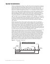
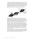
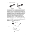
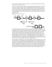
Figure 7.2
An example of wireless transmission and reception.
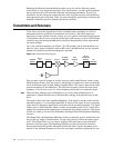
In Figure 7.2, the transmitter is a device that has an input for information, audio, data, or
some other form of intelligence called a source signal, that needs to get from here to there.
The transmitter then takes that information and puts it onto an RF signal. The RF signal is
called a carrier because it, in effect, carries the source signal as it propagates. The process
of actually putting the source signal onto the carrier is called modulating the carrier, which
normally is referred to simply as modulation. The carrier which has had the source signal
applied is then broadcast into the air (actually the electromagnetic spectrum) via an
antenna. The antenna is a transducer that allows the carrier to be efficiently broadcast or
received.
Once the signal is broadcast into the air, it propagates out away from the transmit antenna
and eventually reaches the receive antenna. The area between the transmit antenna and the
receive antenna is called the propagation path, or just path. At the receive antenna, the
signal, which is now much weaker, is collected and enters into the receiver. The receiver’s
job is to find the one unique carrier from the transmitter and strip off the source signal so it
exactly matches the original information. This process is called demodulation.
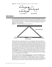
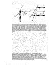
Now, let’s look at the RF wave as it moves along the propagation path. We know that RF
propagates or moves from one point to another, and that propagation can be affected by the
frequency of the wave. Now we’ll find out how RF waves normally act in typical
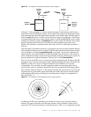
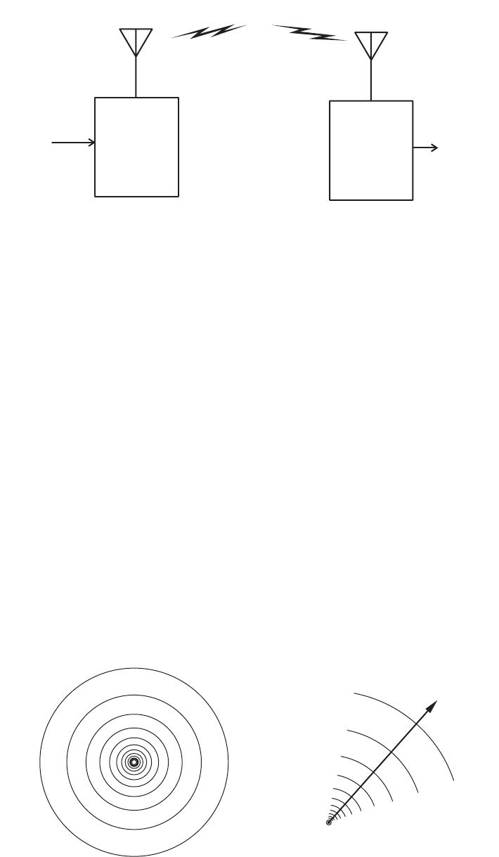
environments. You can think of an RF signal that radiates out into open space from a
specific point, such as a transmit antenna, like the waves generated by throwing a pebble
into a pond as shown in Figure 7.3. The energy carried by the wave moves away from the
original point in all directions equally and each vector that can be drawn from the center
point represents RF energy traveling away from the point of origin in a straight line as
shown in Figure 7.3.
Figure 7.3
An example of electromagnetic waves being radiated.
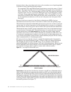
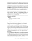
In addition, the RF wave continually gets weaker as it moves away from the transmit
antenna. The rate at which the wave becomes weaker can be calculated via the inverse
square law 1/D
2
where D = distance traveled by the wave. This is a very important concept
TRANSMITTER
RECEIVER
ANTENNA
TRANSMIT
ANTENNA
TRANSMISSION
LINE
TRANSMISSION
LINE
RECEIVER
SOURCE
SIGNAL
COPY OF
SOURCE
SIGNAL