


Chapter 7 - Design of Wireless Intercom Systems 109
Results are calculated and can vary.
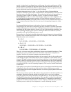
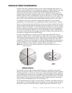
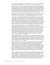
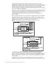
Figure 7.16
The typical parts of coaxial cable.
Installation
Having all the right gear and all the proper frequencies selected is a good first step to
having a top notch, highly effective, wireless communications system. However, having
the right stuff is not enough, it has to be installed properly or it is all for not. In this section
we take the time to cover the most common do’s and don’ts of installing a wireless system
that actually works!
We’ll start with the general conceptual strategy for selecting a location for the RF
equipment to live. Unlike hardwired communications systems, that can be tucked away
almost anywhere, wireless systems must have prime real estate locations due to the
extremely limited length of the coaxial cables that connect the transmitter and receiver to
their respective antennas. As discussed in the previous section, the length of the antenna
cables in a wireless system should rarely exceed 100 feet, and in some cases they should
be kept much shorter due to frequency and cable loss. Because of this, selecting the
location of transmitter and receiver equipment is absolutely critical to system
performance.
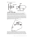
First of all, it is necessary to determine all of areas where coverage is absolutely necessary.
These are the ‘no compromise’ areas, and your system must be designed and installed to
consistently meet or exceed these minimum operational requirements. Anything you can
get after these areas is gravy. Select a location for the wireless base station that is centrally
located in the “must work” area whenever possible. Obstacles like buildings, cars, trees
outside, walls, cameras, lighting, and equipment racks inside all act as factors to limit
range. If they are in the direct line of site between the base station antennas and the
Table 7.1
Coaxial Cable Loss Chart
Attenuation (dB per 100 feet) at the frequency given
220 MHz 450MHz 700MHz 900MHz
Times LMR-400 1.8 2.7 3.4 3.9
RG-8/U 2.94.55.86.7
RG-213/U 3.5 5.2 6.7 8.0
Times LMR-240 3.7 5.3 6.6 7.6
RG-8/X 6.0 8.6 10.7 12.8