


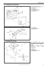
3. INSTALLATION
BAS-300G, BAS-311G, BAS-326G
13
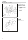
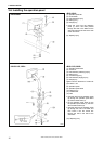
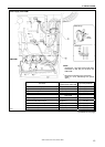
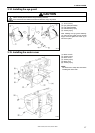
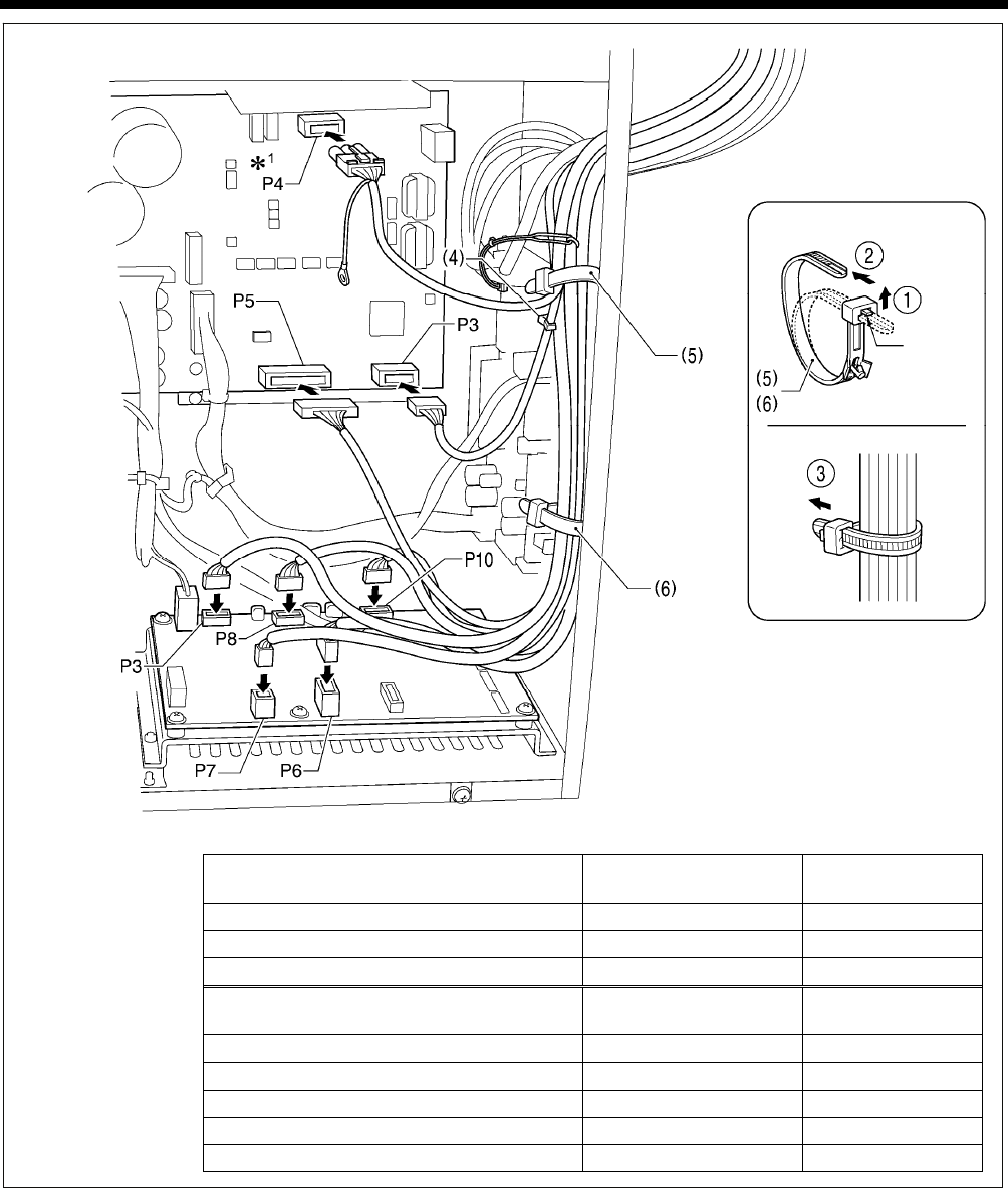
<Power supply motor PCB>
<PMD PCB>
Connector
Connection location on
power supply motor PCB
Cord clamp/cable tie
Machine head memory 7-pin P3 (HEAD-M) (4)
Upper shaft motor 3-pin P4 (UVW) (5)
Synchronizer 14-pin P5 (SYNC) (5), (6)
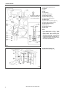
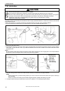
Connector
Connection location on
PMD PCB
Cable tie
Work clamp pulse motor 4-pin black P3 (PPM) (5), (6)
Thread trimmer solenoid 6-pin P6 (SOL1) (5), (6)
Tension release solenoid 4-pin P7 (SOL2) (5), (6)
Y pulse motor 4-pin blue P8 (YPM) (5), (6)
X pulse motor 4-pin white P10 (XPM) (5), (6)
(Continued on next page)
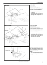
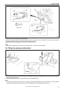
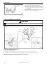
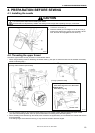
<Removing>
Press
the tab.
<Securing>
1843B
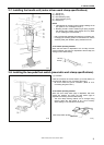
NOTE:
Route the X, Y and work clamp pulse moto
r
harnesses so that they do not touch the
PMD PCB.
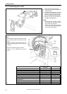
*
1
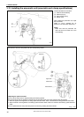
: Be sure to make the ground connection.
(Refer to "3-10. Connecting the ground
wire".)