


3. INSTALLATION
BAS-300G, BAS-311G, BAS-326G
12
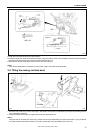
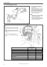
3-9. Connecting the cords
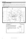
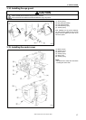
1. Gently tilt back the machine head.
2. Pass the cord bundle through the hole
in the work table.
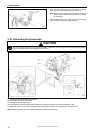
3. Loosen the two screws (1), and then
open the cord presser plate (2) in the
direction of the right arrow and pass
the cord bundle through the opening.
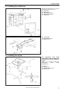
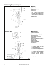
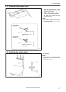
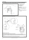
4. Securely connect the connectors as
indicated in the table below.
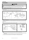
NOTE:
• Check that the connector is facing
the correct way, and then insert it
firmly until it locks into place.
• Secure the cables with cable ties
and cord clamps, while being careful
not to pull on the connector.
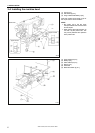
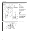
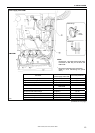
<Main PCB>
NOTE:
• Check that the connector is facing the correct
way, and then insert it firmly until it locks into
place.
• Secure the cables with cable ties and cord
clamps, while being careful not to pull on the
connector.
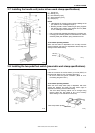
*
1
: Be sure to make the ground connection.
(Refer to "3-10. Connecting the ground
wire".)
Connector
Connection location on
main PCB
Cord clamp
X pulse motor encoder 5-pin white P20 (X-ENC) (3)
Y pulse motor encoder 5-pin blue P4 (Y-ENC) (3)
Work clamp pulse motor encoder 5-pin black P5 (P-ENC) (3)
Foot switch 10-pin P6 (FOOT) (3)
Operation panel 8-pin P1 (PANEL) (3)
Machine head switch 3-pin P9 (HEAD-SW) (4)
Home position sensor assembly 12-pin P8 (SENSOR1) (4)
STOP switch 6-pin P13 (HEAD) (4)
Valve harness 12-pin (pneumatic work clamp
specifications)
P12 (AIR1) (4)
Programmer relay harness 8-pin P7 (PRG) (3)
Solenoid selection harness 4-pin P3(CUTTER) -
(Continued on next page)
4924Q
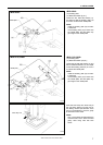
Lock the cord
clamp securely.
1842B