


Technical Data Port Pinouts - Page 65
IP Office Installation Manual Technical Data - Page 65
40DHB0002USCL – Issue 9 (28th October 2003) Port Pinouts
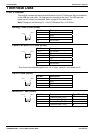
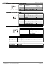
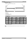
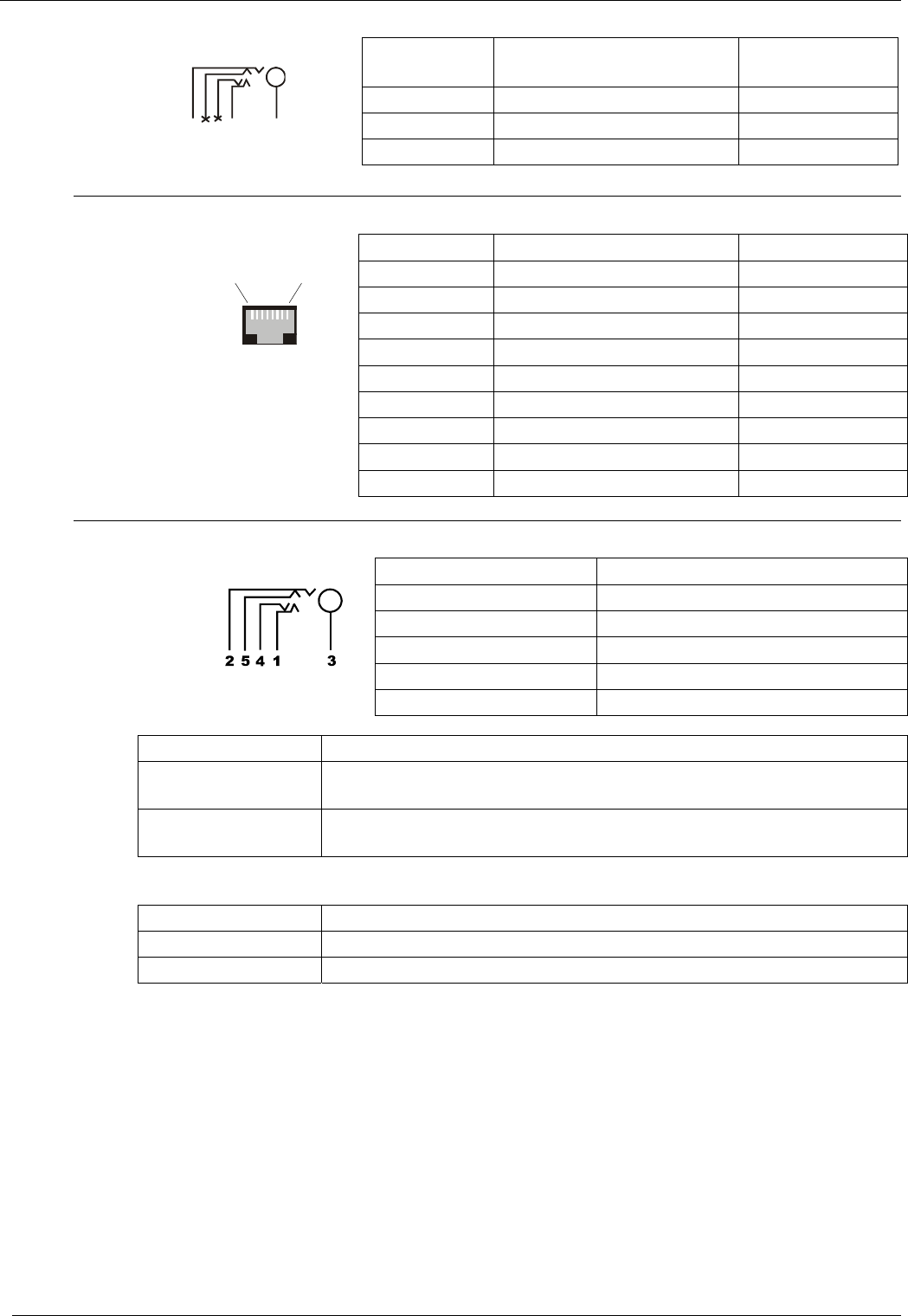
Audio Port (3.5mm Stereo Jack Socket)
Pin No. Description Signal
Direction
Common Common
Left Audio in – Left Channel
Í
Left Right Common
Right Audio in – Right Channel
Í
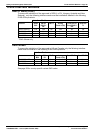
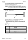
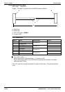
Expansion Port (RJ45 Socket)
Pin No. Description Signal Direction
1 Receive Data (Rx-B)
Í
2 Receive Data (Rx-A)
Í
3 Sync-B
Î
4 Clock (Clk-B)
Î
5 Clock (Clk-A)
Î
6 Sync-A
Î
7 Transmit Data (Tx-B)
Î
8 Transmit Data (Tx-A)
Î
Pin 1
Pin 8
Shield Connected to chassis Ground
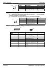
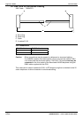
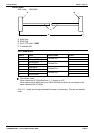
External Control Port (3.5mm Stereo Jack Socket)
Pin No. Description
1 Circuit 1
2 Circuit 2
3 0 Volts (Ground/Chassis)
4 Not Connected
5 Not Connected
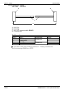
Control Circuit Information
Control Circuit 1 Pin 2 and Pin 3, ensure that Pin 2 is at a positive voltage with
respect to Pin 3.
Control Circuit 2 Pin 1 and Pin 3, ensure that Pin 1 is at a positive voltage with
respect to Pin 3.
Each circuit can be switched independently.
Switch Setting Information
ON Low resistance between Pins.
OFF High resistance between Pins.