


Expansion Modules IP400 Analog Trunk 16 - Page 27
IP Office Installation Manual Expansion Modules - Page 27
40DHB0002USCL – Issue 9 (28th October 2003) IP400 Analog Trunk 16
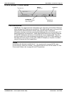
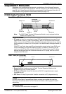
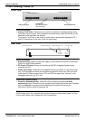
IP400 Analog Trunk 16
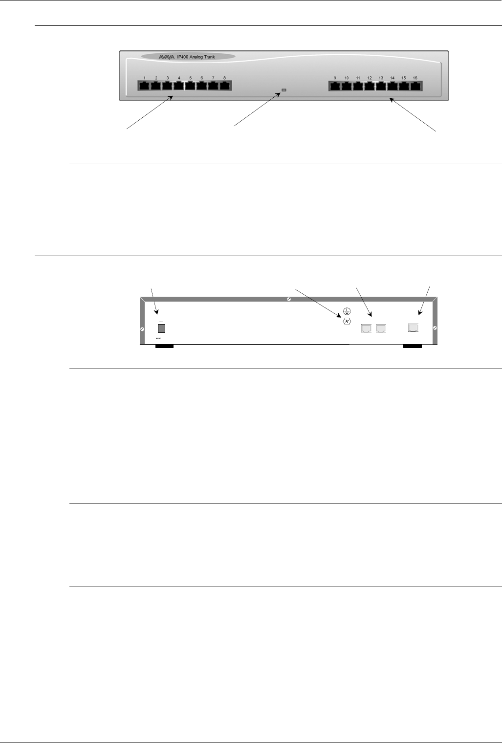
Front View
A
nalog Trunk Ports 1-8
Unit Status LED
Red = Alive but not initiated
Green = Running OK
Analog Trunk Ports 9-16
Port connections
• Analog Trunk Ports: These ports are used for connection to standard analog trunks
(loop start or ground start). Using standard structured wiring, these RJ45 ports can be
extended to the required trunk sockets.
Trunk ports 1 and 2 are, in the event of power failure, automatically switched to PF1
and PF2 respectively on the rear of the unit (see below).
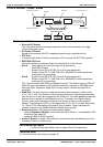
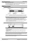
Rear View
Expansion Port
DC Power I/P Socket
EXPANSION
DC I/P
- C +
24V DC
2A
PF2
PF1
Power Fail Trunks 1 & 2
Protective Earth Point
Port connections
• Expansion Port: Used to connect the Analog Trunk Expansion Module an Expansion
Ports of an IP400 Office platform.
• DC Power I/P Socket: Socket for the external 24V DC unregulated power supply
(supplied with kit).
• Power Fail Trunks: These two ports must be set and connected to Loop Start trunks
only. POTs plugged into these two sockets are mapped to trunk ports 1& 2 such that,
in the event of a mains power failure, PF1 and PF2 can operate as 'hot lines' to the
emergency services (e.g. 911, etc).
Protective Ground (Earth)
• Protective Grounding Point: Within the USA a protective grounding must be
permanently fitted. Connection of this protective grounding requires the use of suitable
tools and must be connected at both ends before connection is made to the
telecommunications network (see page 35).
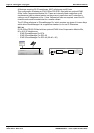
Cables
IP400 Analog Trunk 16 is supplied with one blue Expansion Interconnect cable. For Port
Pinouts and Cables, refer to pages 63 and 67 respectively.