


Technical Data Port Pinouts - Page 63
IP Office Installation Manual Technical Data - Page 63
40DHB0002USCL – Issue 9 (28th October 2003) Port Pinouts
Technical Data
Port Pinouts
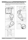
This section provides the technical specifications for the IP Office ports with the exception
of the USB port and cable. All diagrams are viewed from the front. The USB port and
cable (up to 5 meters) are standard. Refer to page 67 for cable details.
Note: Throughout the following, Tx = from IP Office and Rx = to IP Office.
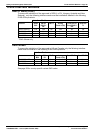
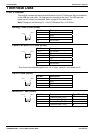
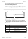
Analog Trunk Ports (RJ45)
Pin No. Description
1-3 Do not use
4 Ring
5 Tip
Pin 1
Pin 8
6-8 Do not use
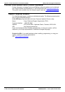
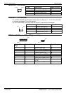
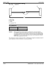
Power Fail and POT Ports (RJ45)
Pin No. Description
1 & 3 Do not use
2 Connected to pin 6*
4 Ring
5 Tip
6 Connected to pin 2*
Pin 1
Pin 8
7-8 Do not use
* Pins 2 and 6 are shorted together and, via a ‘ringer’ capacitor, connected to in 5.
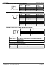
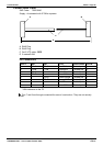
DS/DT Ports (RJ45)
Pin No. Description
1-3 Do not use
4 Sig 1
5 Sig 2
Pin 1
Pin 8
6-8 Do not use
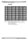
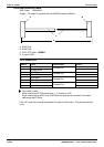
ISDN Port – BRI (RJ45)
Pin No. Description Signal Direction
3 Transmit Data (Tx-A)
Î
4 Receive Data (Rx-A)
Í
5 Receive Data (Rx-B)
Í
Pin 1
Pin 8
6 Transmit Data (Tx-B)
Î