


Page 12 - IP403 Office - Rear View IP403 Office Platform
Page 12 - IP403 Office Platform IP Office Installation Manual
IP403 Office - Rear View 40DHB0002USCL – Issue 9 (28th October 2003)
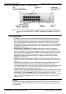
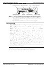
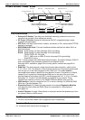
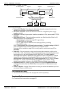
IP403 Office - Rear View
DC Power I/P Socket
DTE Port
WAN Port
Slot A is normally blank, but can
contain an ANALOG Trunk Module
Slot B can contain either an ANALOG
or BRI or PRI Trunk Module
Slot B
AUDIO
EXPANSION
1 2 3
DTE
WAN
EXT
O/P
DC I/P
-
C +
24V DC
2A
Slot A
External O/P Socket
PRI
ANALOG TRUNK
1 2 3 4
BRI
1 2 3 4
USB Interface Socket
Expansion Ports 1-3
Audio I/P Socket
Port connections
• External O/P Socket: Two relay ports that allow externally powered circuits to be
controlled via a single 3.5mm stereo jack socket.
• DC Power I/P Socket: Socket for the external 24V DC unregulated power supply
(supplied with equipment).
• DTE Port: A 25-way D-type socket. Used for connection to PCs, servers and EFTPOS
devices or terminals.
• BRI/PRI/ANALOG Ports: The trunk interface modules are fitted into either Slot A or
Slot B as follows:
Slot A Quad Analog: 4 trunks (see page 35 for grounding)
Slot B Quad Analog: 4 trunks (see page 35 for grounding)
PRI E1/PRI E1-R2: 30 trunks
PRI T1: 24B trunks or 23B+1D trunks (see page 35 for grounding)
Quad BRI: 8 trunks.
PRI T1 trunks support both ISDN and Analog emulation. The default setting is 23B+1D
and is switchable in the installation software to provide 24B trunks.
See page 40 for installation, page 29 for country specific variants and page 35 for
grounding.
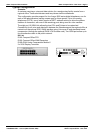
• WAN Port: This port supports a single synchronous data connection, which can be
X.21, V.35 or V.24. The selection of the required interface is automatically determined
from the pin-out of the cable plugged into the ‘WAN’ port. This cable must be
connected before power is applied for auto detection to work. Connection to a Digital
Leased Circuit is made by connecting the WAN port on the rear of the unit to the
existing Network Terminating Unit (NTU) via the appropriate X.21, V.35 or V.24 cable.
See pages 74, 75 and 76 for cable details and page 66 for port details. These
interfaces are identical to those on the WAN3 Extension Module (see page 26).
• USB Interface: Used for connection to a PC or server, allowing it to utilize the IP403
Office as a Terminal Adapter (TA).
• Expansion Ports 1-3: Used to provide access to the optional Expansion Modules
(see page 23) which allow the IP403 Office to be expanded to 100 extensions
(see page 10).
• Audio I/P Socket: A single 3.5mm stereo or mono jack socket that enables input from
an external 'Music-on-Hold' source.
Port Pinouts and Cables
• For Port Pinouts and Cables, refer to pages 63 and 67 respectively.
Functional Earth
For Functional Earth connections see page 35.