


Page 26 - IP400 WAN3 Expansion Modules
Page 26 - Expansion Modules IP Office Installation Manual
IP400 WAN3 40DHB0002USCL – Issue 9 (28th October 2003)
IP400 WAN3
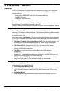
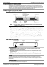
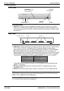
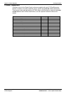
Front View
Unit Status LED
Red = Alive but not initiated
Green = Running OK
WAN Link Status 1 - 3
Green LE
D
LAN Link O
K
LAN Por
t
Yellow LE
D
LAN Activity Indicato
r
Port connections
• LAN Port: The LAN Port is the expansion port and permits connection to an IP403,
IP406 or IP412 Office platform LAN Port. A LAN Interconnect cable (see page 70) is
required for connection to an IP403 or IP406 and an IP412 requires a Crossover cable
(see page 72).
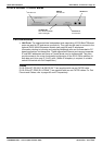
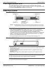
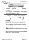
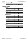
Rear View
DC I/P
- C +
24V DC
2A
DC Power I/P Socket
DTE Port
DTE
WAN 1 WAN 1
WAN 1
WAN Ports 1-3
Port connections
• WAN Ports: These ports support a single synchronous data connection, which can be
X.21, V.35 or V.24/V.28. The selection of the required interface is automatically
determined from the pin-out of the cable plugged into the WAN port. This cable must
be connected before power is applied for auto detection to work. Connection to a
Digital Leased Circuit is made by connecting the WAN port on the rear of the unit to the
existing Network Terminating Unit (NTU) via the appropriate X.21, V.35 or V.24 cable.
These cables are detailed in the table below (see pages 74, 75 and 76 for details).
Cable Type SAP Code
V.24/V.28 Cable 700213416
V.35 Cable 700213408
X.21 Cable 700213424
These WAN ports are identical to those on the IP403/406/412 Office platforms (see
pages 12, 16 and 20).
• DC Power I/P Socket: Socket for the external 24V DC unregulated power supply
(supplied with kit).
• DTE Port: A 25-way D-type socket. Used for connection to PC (as a diagnostic aid).
Cables
IP400 WAN3 is supplied with one green LAN Interconnect cable. For Port Pinouts and
Cables, refer to pages 63 and 67 respectively.
Functional Earth
For Functional Earth connections see page 35.