


Page 24 - IP400 Digital Stations 16/30 Expansion Modules
Page 24 - Expansion Modules IP Office Installation Manual
IP400 Digital Stations 16/30 40DHB0002USCL – Issue 9 (28th October 2003)
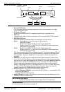
IP400 Digital Stations 16/30
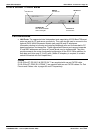
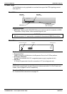
The IP400 Digital Station Expansion Module similar to the IP400 Digital Terminal
Expansion Module (see page 23) with the exception that the Ports are labeled DS not DT
and support Avaya 6400, 2420 or 4400 series telephones.
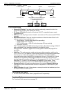
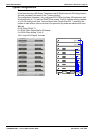
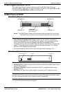
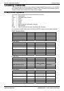
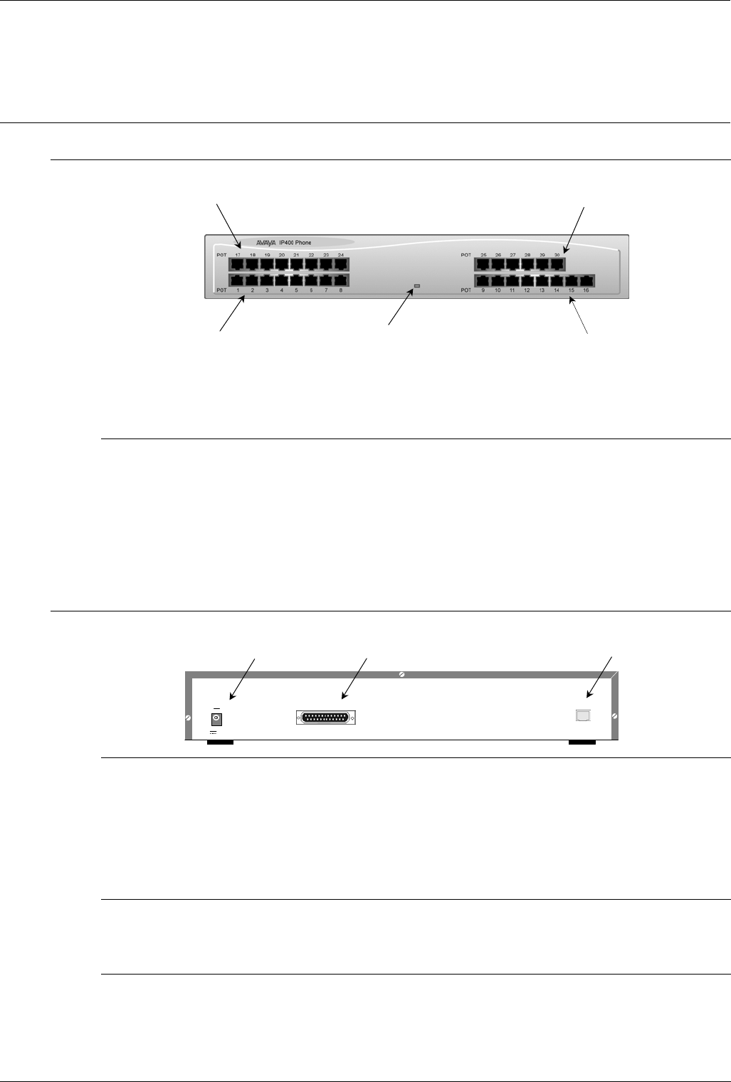
IP400 Phone 8/16/30
Front View (30 port version)
Phone Ports 1
- 8
Unit Status LED
Red = Alive but not initiated
Green = Running OK
Phone Ports 17
- 24
Phone Ports 9
- 16
Phone Ports 25
- 30
Notes: The IP400 Phone 8 variant is only equipped with the bottom left row of ports.
The IP400 Phone 16 variant is only equipped with the bottom row of ports.
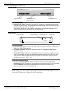
Port connections
• Plain Ordinary Telephone (POT) Ports: These ports are used for connection to
standard analog telephones, fax machines and modems. Using standard structured
wiring, these RJ45 ports can be extended to the required telephone location.
Converters can be used to provide BT New Plan sockets (431A/631A) if required (see
page 77). When devices are equipped with line cords that terminate in RJ11 plugs,
then RJ11/RJ45 adapters should be used.
• All analog telephones must conform to the port specification (see page 79).
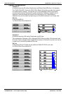
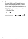
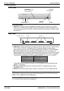
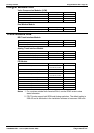
Rear View (all versions)
EXPANSION
DTE
Expansion Port
DTE Port
DC Power I/P Socket
DC I/P
- C +
24V DC
2A
Port connections
• Expansion Port: Used to connect a Phone Expansion Module to the Expansion Ports
of an IP Office platform.
• DC Power I/P Socket: Socket for the external 24V DC unregulated power supply
(supplied with kit).
• DTE Port: A 25-way D-type socket. Used for connection to PC (diagnostics only).
Cables
All IP400 Office Phone variants are supplied with one blue Expansion Interconnect cable.
For Port Pinouts and Cables, refer to pages 63 and 67 respectively.
Functional Earth
For Functional Earth connections see page 35.