28
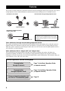
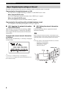
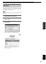
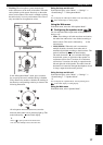
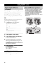
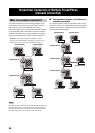
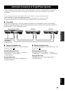
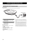
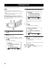
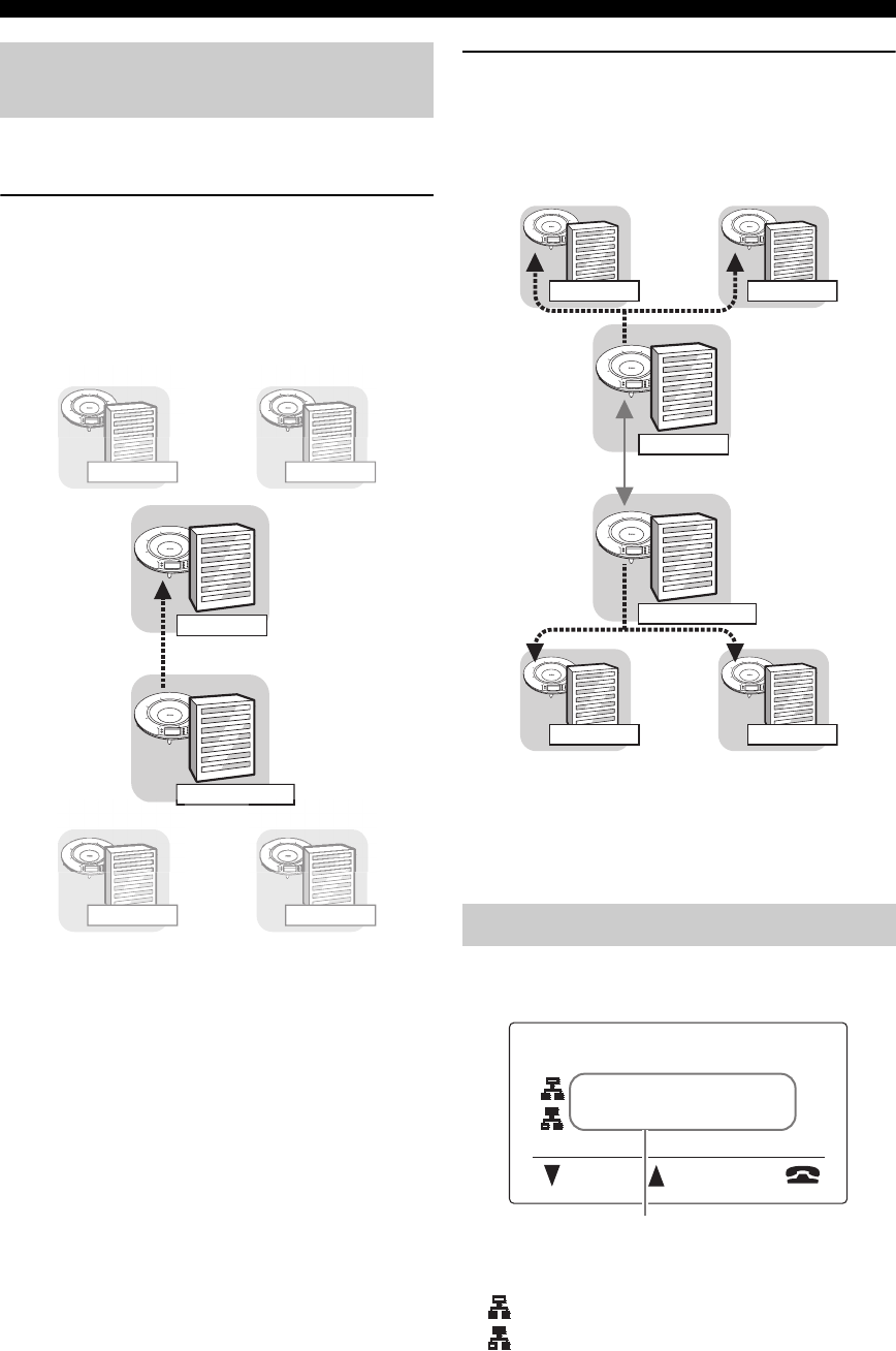
Hierarchical Connection of Multiple ProjectPhone (Cascade Connection)
When the cascade connection is used, the calls can be
placed using the following procedure.
1 Call the master unit in another location from
the cascade master unit.
The calling method is the same as ordinary calling.
See page 7 in the “Basic operation guide” (a separate
manual) for details.
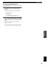
2 After the communication is established, call
each of the slave units connected to the
Cascade master unit.
The calling method is the same as ordinary calling.
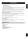
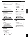
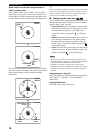
y
You can also call the slave units connected to the cascade
master unit before calling the master unit in another
location.
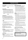
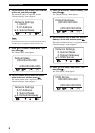
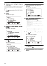
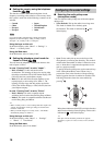
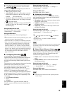
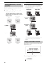
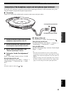
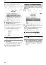
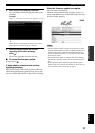
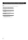
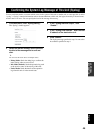
The IP addresses of other units connected to this unit are
displayed during a call.
The mark displayed before each IP address indicates the
cascade connection mode of each unit.
• : “Cascade Server”.
• : “Cascade Client”.
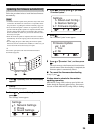
Communication using a cascade
connection
1
2
3
4
5
6
7
8
9
0
MIC MUTE
VOL
1
2
3
4
5
6
7
8
9
0
MIC MUTE
VOL
Cascade Server
(Master)
Cascade Server
(Master)
Headquarter
Branch
Cascade Server
(Slave)
Cascade Server
(Slave)
Cascade Server
(Slave)
Cascade Server
(Slave)
Div. (d)Div. (c)
Div. (a)
Div. (b)
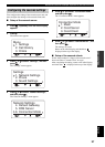
Display in cascade connection
1
2
3
4
5
6
7
8
9
0
MIC MUTE
VOL
1
2
3
4
5
6
7
8
9
0
MIC MUTE
VOL
1
2
3
4
5
6
7
8
9
0
MIC MUTE
VOL
1
2
3
4
5
6
7
8
9
0
MIC MUTE
VOL
1
2
3
4
5
6
7
8
9
0
MIC MUTE
VOL
1
2
3
4
5
6
7
8
9
0
MIC MUTE
VOL
Cascade Client
(Slave)
Cascade Client
(Slave)
Cascade Server
(Master)
Cascade Server
(Master)
Cascade Client
(Slave)
Cascade Client
(Slave)
Div. Div.
Div. Div.
Headquarter
Branch
Menu :Address
192.168.100.20
192.168.100.30
IP address of other units