INSTALLATION-DK8 KSU & PCB
SECTION 100-816-204
MARCH 1993
4-12
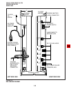
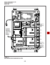
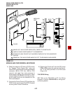
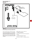
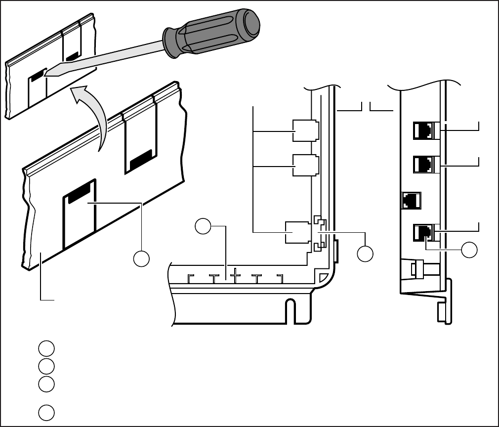
FIGURE 4-9
MODULAR JACK COVER REMOVAL AND STORAGE
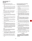
4) Slide front edge and FG wire of QCDU under
the "System Frame Ground Bar", align and
insert QCDU connector J1 into the motherboard
connector (J9 for CO3 first, J10 for CO4
second), and apply firm, even pressure to
ensure proper mating of the connectors. Make
sure the edge of the QCDU next to the connec-
tor J1 snaps firmly into the standoffs on the
KSU motherboard.
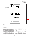
5) Connect the Frame Ground (FG) lead from the
QCDU to the screw nearest the QCDU located
on the system Frame Ground bar.
6) Remove the "knock-out" from the KSU cover
CO3 or CO4 access slot, and store the "knock-
out" in the slots provided in the KSU base
(Figure 4-9).
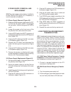
7.30 QCDU Wiring
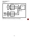
7.31 Refer to the DK8 MDF to CO Line Wiring
Diagram in Section 100-816-208 for wiring/inter-
connecting details.
KNOCK OUT JACK COVER WHEN OCDU, SMDR/TTY IS INSTALLED
TAKE OUTJACK COVER WHEN PFT IS CONNECTED
STORE THE JACK COVER THAT HAS BEEN TAKEN OUT IN THE JACKCOVER
HOLDER
REINSTALL THE JACK COVER WHEN THE PFT TELEPHONE IS UNPLUGGED
MODULAR
JACK
BASE
C02
COVER
C01
PFT
1
2
3
2
1
3
4
4


