6-13
INSTALLATION-STATION APPARATUS
SECTION 100-816-206
MARCH 1993
the base (Figure 6-1). The HHEU modular
connector for the headset will be accessed
through this opening.
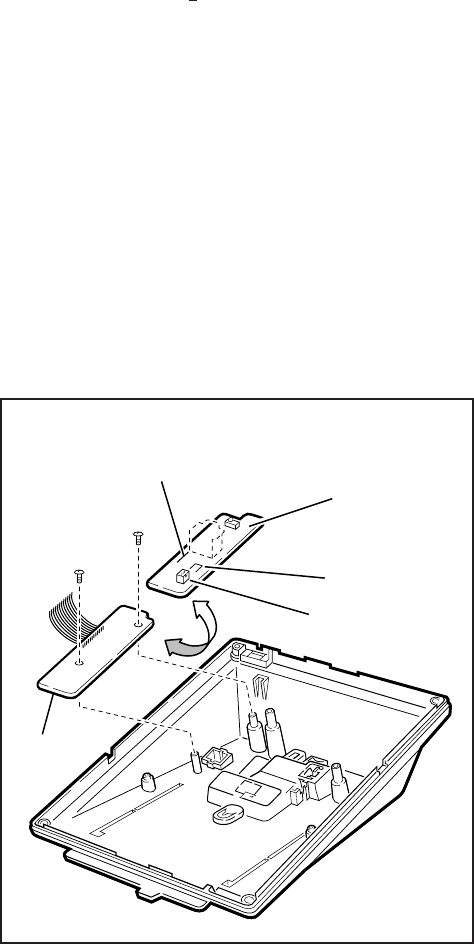
3) If using a V.3 or earlier HHEU1, set the
SW601 switch to the HEADSET position for
HESB and/or headset connection (Figure 6-
15). This switch is not on either the V.4
HHEU1 or the
HHEU2, because the opera-
tion is automatic with these subassemblies.
4) Connect the HESC-65 or HESC-65A cable
(either one) to P601 of the HHEU if the Loud
Ringing Bell option is required (Figure 6-11).
Refer to Section 100-816-207 for HESB in-
stallation procedures.
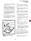
5A) For the V.3 or earlier HHEU1: If only the
headset is connected to the HHEU, cut both
sides of the R607 resistor on the HHEU
(Figure 6-15) and then remove the resistor to
eliminate electrical contact.
NOTE:
Do not cut the R607 resistor if connecting an
HESB to the HHEU for the Loud Ringing
Bell—even if a headset is also installed on the
HHEU.
5B) For the V.4 HHEU1 or the HHEU2: If only the
headset is connected to the HHEU, cut the
OCA strap (Figure 6-15).
NOTE:
Do not cut the OCA strap if connecting an
HESB to the HHEU for the Loud Ringing
Bell—even if a headset is also installed on the
HHEU.
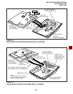
6) Position the HHEU subassembly on the stand-
offs inside the base (Figure 6-15), and secure
with the two provided screws.
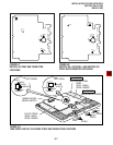
7) Connect the HHEU subassembly wire plug to
the P1 connector on the electronic telephone
PCB (Figure 6-13).
8) Cut the HHEU strap on the telephone PCB
(Figure 6-13).
NOTE:
The HHEU strap must be replaced if the
HHEU PCB is removed from the telephone.
9) Reinstall the telephone base, and secure it
with its four captive screws.
10) To adjust the volume of the HESB Loud
Ringing Bell: Call the telephone connected to
the HESB, and adjust the volume control on
the back of the HESB and the ring volume
control on the telephone.
4.30 Carbon Headset/Handset Straps
4.31 If a carbon-type handset or headset is con-
nected to the handset jack on the side of the 6500-
series electronic telephone, two straps inside the
telephone must be cut. Cut the straps in accor-
dance with the following steps:
NOTE:
It is not necessary to cut these straps if the
headset is connected to the HHEU.
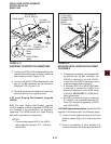
FIGURE 6-15
HHEU INSTALLATION FOR ELECTRONIC
TELEPHONES
HHEU
COMPONENT SIDE OF HHEU
SW601
P601
R607 (HHEU1 V.1 ~ V.3)
OCA (HHEU1
(HHEU1A V.1 ~V.3)
V.4 or HHEU2)
TO P1, HHEU
CONNECTOR
OF
TELEPHONE
PCB


