INSTALLATION-PERIPHERALS
SECTION 100-816-207
MARCH 1993
7-27
Disconnect Timer:
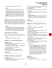
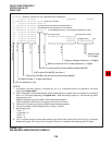
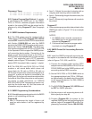
01 DISA 12:24 00:04;57 (incoming)
03 DISA 12:24 00:04;57 (outgoing)
6.03 System Program Data Printout. If a printer
is connected to the SMDR port on the QSMU,
PIOU, or PIOUS, customer program information
stored in the system RAM may be printed out for
reference by using Program 97 (see Paragraph
6.14).
6.10 SMDR Hardware Requirements
6.11 The DK8 system must be equipped with a
QSMU option PCB. QSMU Program 10-3, LED 04
must be OFF. Install the QSMU PCB in accordance
with Section 100-816-204 and wire the SMDR
device to the QSMU (PPTC/mocular cord) in accor-
dance with Section 100-816-208. The DK16 sys-
tem must be equipped with a PIOU or PIOUS PCB
in the Expansion Unit to support the SMDR printer/
call accounting device option. Connection of the
printer or call accounting device to the PIOU or
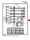
PIOUS PCB is accomplished with a 3-pair modular
cord (7 feet maximum) and a PPTC connector
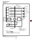
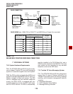
adaptor (refer to Figure 7-20 for details). Call record
data is ASCII-formatted, 8 bits, no parity, 1-stop bit.
6.12 The DK8 KSU and DK16 PIOU or PIOUS
contains a call record buffer which stores call
record data (for 20 calls on DK8 or 50 calls on
DK16) when the printed or call accounting device is
turned off, or when no device is connected to the
SMDR port. No further call records are stored after
the buffer is filled. When the printer or call account-
ing device is made operational, an “ERROR
BUFFER OVERFLOW” message is printed to indi-
cate that the buffer was full, and that some call
information may have been lost.
6.13 SMDR Programming Considerations
6.14 Selectable programming options for the SMDR
printer or call accounting device are:
Program 60
Item 2—Determines the length of time a call
must be active before it will be registered by
SMDR.
Item 3—Selects the records of outgoing calls or
outgoing and incoming calls to be printed.
Item 4—Selects digit length of account code (4 to
15 digits).
Item 5—Allows only long distance call records to
be printed.
Program 97
Allows system program data to be printed via the
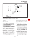
SMDR port (refer to Figure 7-21 for an example
printout).
NOTES:
1. An SMDR printer must be connected to
the SMDR port to use the printout option
selected by Program 97.
2. Call record data is lost when program data
is printed out using Program
97
.
6.20 SMDR Printer/Call Accounting Device In-
stallation
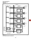
6.21 Install the SMDR printer/call accounting de-
vice option in accordance with the following steps
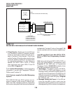
(refer to Figures 7-20, 8-26, and 8-24):
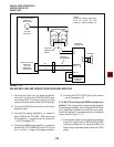
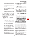
1) Connect the interface cable and the PPTC
adaptor from the DK8 QSMU or DK16 PIOU or
PIOUS SMDR port to the SMDR printer or call
accounting device DB25 connector.
2) Set the DK16 PIOU or PIOUS SW1 switch to
the appropriate baud rate (300 or 1200 bps),
as determined by the baud rate of the printer
or call accounting device. For DK8, QSMU is
always 1200 bps.
3) The DK8 QSMU Program 10-3, LED 04 must
be OFF for SMDR operation.
4) Set the printer or call accounting device to 8-
bits/no parity/one stop bit.
5) Program (Program 60) the system for the
required SMDR printer/call accounting device
options (refer to Paragraph 6.13 and the Pro-
gramming Procedures, Section 100-816-300).


