INSTALLATION-PERIPHERALS
SECTION 100-816-207
MARCH 1993
7-57
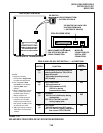
NOTES (Amplifier):
1.
2.
3.
4.
NOTES (PROGRAMMING):
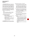
• Program 10-3, circuit assignments
• Program 10-1, LED 19 and 20 ON.
• Program 15-5, enable appropriate CO lines for
tandem connection.
• Program 78-2, enable appropriate CO lines if
amplified DISA is required.
• Program 10-2, LED 18 and 19 ON.
PROGRAM 10-3
PESU/PEKU PORT
CONF. ENABLE
BUTTON/LED
LED 02, ON
PESU OR
PEKU SLOT
POSITION
04
PESU OR
PEKU PORT
NUMBER
PESU OR
PEKU
CIRCUIT
A = 17
B = 18
CKT6
CKT7
PUBLIC
TELEPHONE
NETWORK
CKT, X
PCM
CONFERENCE
SWITCH
T
R
CO
LINE
VT(6), P36/BK-BL T, P51
24AWG
TWISTED
PAIR
VR(6), P11/BL-BK
DT(6)
DR(6)
NOT USED
R, P33
PORT A
(CKT 6)
CKT, Y
T
R
VT(7), P38/BK-GN T, P41
VR(7), P13/GN-BK
DT(7)
DR(7)
NOT USED
R, P49
PORT B
(CKT 7)
OUTSIDE
PARTY 1
OUTSIDE
PARTY 2
ANY
STATION
CALL
AMP
POWER
SUPPLY
–24
GND
P35
P17
R-TEC, PS16
POWER ADAPTER
(NOTES)
+
24VDC
–
117VAC
60HZ
DUPLEX
AC-PLUG
SYSTEM
TELEPHONE
THAT SETS UP
2-CO LINE
CONFERENCE
CALL
CKTA
24AWG
25-PAIR
CABLE
R-TEC, VFR5050
AMPLIFIER
(see NOTES)
R-TEC EDGE
CONNECTOR
MDF
BASE UNIT
PESU or
PEKU
ANY CO LINE
MAY BE USED FOR
CONFERENCE; SEE
PROGRAMMING NOTES
FOR TANDEM AND/OR
DISA CO LINES
CKTB
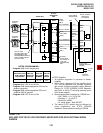
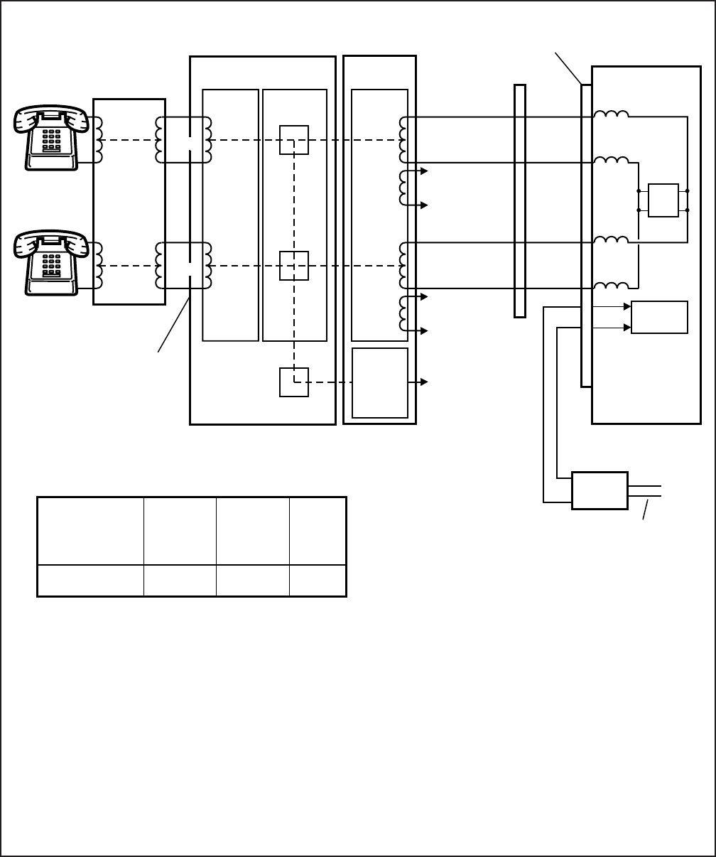
All amplifier equipment is customer or dealer-
supplied.
Use a 2-way, telephone CO line amplifier that is
FCC Part 68 registered and provides automatic
gain control; the above example is with a Reliance
Electric Co., R-TEC VFR5050 (VVSG) Repeater,
with 500-X or 500-X-CT mounting assembly and a
PS16 power adapter.
Recommended switch settings for VFR5050 are:
• FLAT GAIN (1, 2, 4, 8): all ON
• Equalizer (1 ~ 5): all OFF
• Sensitivity: NORM
• S1 screw: down = Data DIS OFF
The above R-TEC options may be different for
some installations; see R-TEC VFR5050
installation Practice before installing VFR5050.
CO
LINE
SLOT 04
EXPANSION
UNIT
FIGURE 7-39
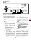
DK16 AMPLIFIED TWO-CO LINE CONFERENCE AND/OR AMPLIFIED DISA FUNCTIONAL WIRING
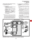
DIAGRAM


