REMOTE ADMINISTRATION AND MAINTENANCE PROCEDURES
SECTION 100-816-600
MARCH 1993
-10-
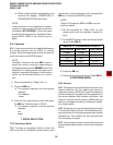
When communication is established, the
terminal will display: CONNECTED or
COMMUNICATIONS (see Note).
NOTE:
If the connection is not completed or commu-
nication is unsuccessful, the remote terminal
will display:
NO CARRIER.
If this is the case,
check that the equipment is installed per Para-
graph 5.10 or 6.10 of this section and try
again.
6.30 Operation
6.31 Once communication is established between
the remote terminal and the IMDU or external
modem, follow the steps below to enter the security
code and receive the MODE prompt.
NOTE:
Hereafter, whenever the term
CR
is used, it
means the return or enter key, depending on
the keyboard being used.
SPACE
means the
space bar. An empty square indicates one of
several characters will appear in that location
(either on the terminal’s screen or in a print-
out).
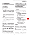
1) Set the keyboard for “Caps Lock” on.
2) Press the CR key.
The system responds, and the terminal
displays:
DK CONNECT
>CODE
3) Enter the four-digit security code and press
the CR key. (Default code is “0000”.)
The system responds, and the terminal
displays:
OK
MODE
7 MODE SELECTION
7.00 Selecting a Mode
7.01 To enter an operating mode for either the
DK8 or the DK16, establish communication with
the terminal, enter the security code, and press the
CR key to receive the MODE prompt.
NOTE:
Refer to Paragraphs 5.20 or 6.20 to accom-
plish the above.
1) Set the keyboard for “Caps Lock” on (the
mode name must be entered in capital let-
ters).
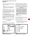
2) At the MODE prompt, enter the desired mode
name (Table RM-C).
3) Press the CR key.
4) Verify the correct prompt return (Table RM-C).
8 PROGRAM MODE
8.00 General
8.01 Data governing overall system operation and
feature execution for the systems are stored in
read-only memory (ROM) and cannot be altered in
the field. However, the data controlling operation of
the various options, both system and station, are
stored in random-access memory (RAM) and can
easily be changed according to individual installa-
tion requirements.
8.02 All options are controlled by selections made
in the System Record Sheet. An initialization proc-
ess is provided for verifying predetermined system
assignments. The installer can then proceed with
any necessary changes.
8.03 Internal battery power is provided to prevent
loss of system data memory in the event of a power
failure.
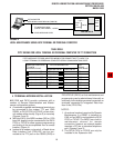
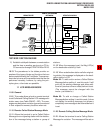
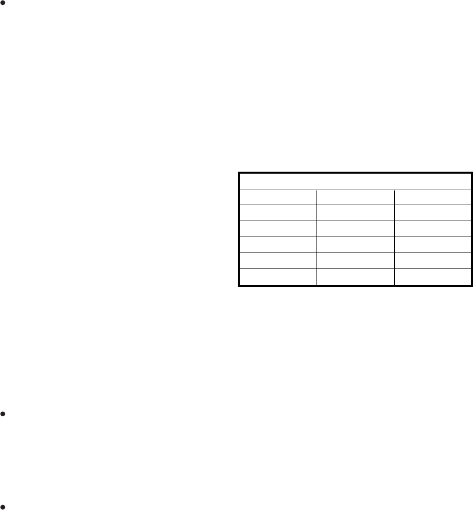
TABLE RM-C—PROGRAMMING PROMPTS
Mode Function Mode Name Prompt Return
Program
Data Dump
Test
LCD Messages
Speed Dial No.
PROG
DUMP
TEST
MESG
REPT
P
D
T
(NONE)
R


