


PN: 1725-36122-001_M.doc
59
Installation Forms
This section contains the following forms:
• Site Preparation Checklist
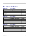
• Base Station Location Worksheet
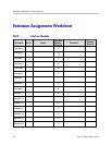
• Extension Assignments Worksheet
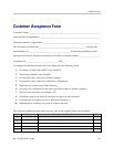
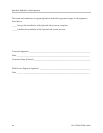
• Customer Acceptance Form
Copy these forms as needed. Be sure to maintain completed forms for
future reference.
Site Preparation Checklist
If upon arrival the Polycom field service engineer determines that the
pre-installation work has not been completed correctly, the engineer
has two options: 1) the engineer can leave the site and reschedule the
installation when the action items have been completed or corrected,
or 2) the engineer can assist in preparing the site, and thus spend
additional time installing the system. Because of the additional cost
incurred by Polycom in executing either option, the customer will be
billed for the additional time at the standard hourly rate plus
expenses.
Please be sure the following items are completed.
MCU location prepared. Typically the MCU is installed in the
telephone equipment room. This location must have sufficient
rack or backboard space and power available.
Two-pair wires are run to each of the Base Station locations as
designated on the building floor plans. Use Level 3 cable for
lengths up to 3,500 feet; Level 4 for lengths up to 6,000 feet.
The Base Station cables are terminated with RJ-45 crimp-on plugs
at the designated locations.
One (or two) cross-connect block(s) are installed for every
Interface Module and connected with a 25-pair Telco cable
terminated with an RJ-21 male connector at the MCU location.
10