


SpectraLink 6300 MCU: Facility Preparation
PN: 1725-36122-001_M.doc
42
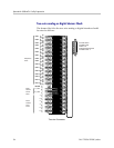
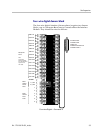
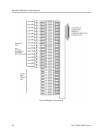
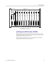
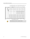
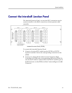
Install Intershelf Junction Panel
The Intershelf Junction Panel (JPI300) is to be installed only in
restricted access areas (dedicated equipment rooms, equipment
closets, or the like), in accordance with Articles 110-16, 110-17, and
110-18 of the NEC, ANSI/N FPA 70.
The expansion shelf controllers of shelves 2 through 20 are connected
to the system controller by an intershelf junction panel. The panel
converts the RJ-21 connections on the system controller to the RJ-45
connections on the expansion shelf controller.
Install the panel in the rack or on the wall adjacent to the Primary
Shelf, which contains the system controller (CSC306 or CSC320).
Wall mounting requires 1.75” #8 panhead wood screws. The panel
must be mounted with standoffs at least 1.5” long and 1/4” inside
diameter.
Connect Power to Shelves
Polycom recommends that a licensed electrician install the -48V DC
power supply and connect power to the shelves.
When connecting the -48 V DC system to power, note the following
precautions:
A 30 amp circuit breaker must be present on the non-grounded DC
circuit conductor, and the installer must ensure that means are
provided for connection of the equipment to the DC source by
permanent wiring methods, and no disconnecting device is located
in the grounded DC circuit conductor between the point of
connection to the supply and the point of connection to the
grounding electrode and equipment grounding conductors.
The DC input to the power supply is polarity sensitive. Incorrect
hookup will prevent normal operation of the system and may cause
damage. Double check polarities before making any connections.
Verify that the DC power switch on each shelf is OFF.