


SpectraLink 6300 MCU: Facility Preparation
PN: 1725-36122-001_M.doc
44
Before turning on the power switch, use a voltmeter to verify that
the terminal labeled -48V is negative with respect to the terminal
labeled +48V.
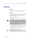
Install Cards
Cards contain components that may be damaged by electrostatic
discharge. Before handling any of the cards, the installer must
attach the grounding strap (included in the Administration Kit) to his
or her wrist, and attach the other end of the strap to ground. Only
handle the cards by their edges. Do not touch connector contact
areas, do not lift cards by any of the components, and do not lay
cards down on their component sides. When laying a card down,
place it component side up on top of the anti-static bag in which it
was shipped.
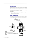
Install System Controller Card
(CSC301, CSC306, CSC320)
Slide the System Controller Card into slots 1 and 2 of the Primary
Shelf, until the card clicks into place. Tighten the screws at the top
and bottom of the card to secure it.
Install Interface Modules
(CPA, CPU, CPM, CPP, CPF316)
Slide the first Interface Module into slot 3 of the Primary Shelf, until
the card clicks into place. Tighten the screws at the top and bottom of
the card to secure it.
Slide additional Interface Modules into their slots. Slots can be left
empty if desired.
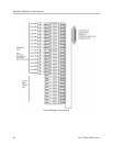
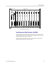
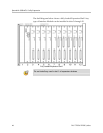
The shelf diagram below shows a fully loaded Primary Shelf. Any
type of Interface Module can be installed in slots 3 through 12.