


SpectraLink 6300 MCU: Facility Preparation
PN: 1725-36122-001_M.doc
32
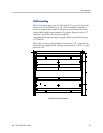
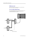
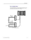
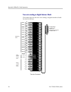
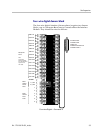
Install Demarc Blocks
The demarcation blocks used to connect the telephone system and
Base Stations to the MCU should be installed on a typical telephone
facility backboard. A 1/2” or 3/4” thick board mounted on the wall
near the MCU is typical. Although this manual uses 66 blocks as
examples, any standard cross-connect blocks are acceptable.
If the wiring between the MCS300 and the telephone system leaves
the building, consult the telephone system manual, the NEC, and
local codes for instructions on providing lightning and other over-
current protection.
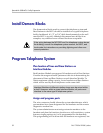
Program Telephone System
Plan location of lines and Base Stations on
Interface Modules
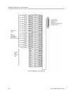
Each Interface Module can support 16 handsets and six Base Stations.
Consider the usage and traffic patterns at this site in determining the
placement of lines and Base Stations on each Interface Module. To
obtain maximum calling capacity, locate handsets and Base Stations
which will be used by those telephones on the same shelf.
Interface Modules of different interface types may be mixed within
a shelf. However, within a given Interface Module, all ports must
interface to the same type of telephone system.
Assign and program ports
The wire contractor should inform the system administrator which
port numbers have been designated for the handsets and the remote
diagnostics modem line.
The system administrator must assign extension numbers to the
handsets and plan the functions (trunk access, toll restrictions, system
features, ringing options etc.) to be programmed for the handsets.
This programming will be done after the handsets are registered, but