


Site Preparation
PN: 1725-36122-001_M.doc
33
will be faster if it is planned in advance by verifying the parameters
and features on the current telephone system and-wired phones.
For details, refer to the LinkPlus Interface Guide for the type of
telephone system for the system controller in use.
Connect Cables from Base Stations and Phone
Lines to Demarc Blocks
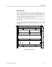
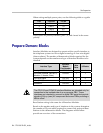
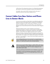
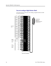
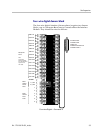
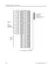
Two-pair twisted cable from Base Stations installed throughout the
facility converge at the demarc block or backboard. Each Interface
Module can support six Base Stations and 16 handsets. The Base
Station and handset cables are punched down onto the Interface
Module cross-connect blocks as shown in the demarc block diagrams
below.
Photocopy the Base Station Location Worksheet and Extension
Assignments Worksheet as needed. Use the forms to track the Base
Stations and handset port assignments connected to each Interface
Module. As the field service engineer punches down each Base
Station or handset connection, fill in the information on the form to
identify the position of the Base Station or handset (the building and
floor number, for example) and a detailed description of the location
(perhaps a room number). A copy of this form should be posted near
the cross-connect block.
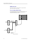
Up to six Base Stations can be connected on a single Interface
Module. Each Base Station uses two pair; one for data and one for
power, so 12 pairs will be used to wire six Base Stations.
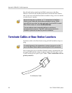
When wiring an external Base Station or a Base Station with wiring
that exits the building, protect all Base Station wiring with the Quick
Clip Fuse (Reliable Electric RSCP-2) before bridging with other
Base Station power leads.
If the wiring between the MCS300 and the telephone system leaves
the building, consult the telephone system manual, the NEC, and
local codes for instructions on providing lightning and other over-
current protection.