


Site Preparation
PN: 1725-36122-001_M.doc
23
• Space for the shelves, which are designed for 19” rack or wall
mounting.
• Each shelf measures 15” high x 19” wide x 9” deep, and weighs
approximately 35 pounds fully loaded.
• Expansion shelves cannot be located more than 17 cable feet from
the Primary Shelf.
• All digital interface modules must be within 250 feet of the
telephone system.
• See your telephone system specifications for distance limitations
for analog modules.
• Location of the Intershelf Junction Panel (JPI300) adjacent to the
shelves on a multi-shelf system.
• The Primary Shelf containing the System Controller (CSC or
CSO306 or 320) must be mounted to allow connection to the
JPI300 with a five-foot cable.
• Expansion Shelves (CSC300 or CSO300) must be mounted to allow
connection of the shelf to the JPI300 using 12 feet or less of
cabling.
• Space for the -48V power supply connections. Power supply
conduit requires clearance of 1.5” on the rear or side of the
shelves.
• Maximum loop length specifications of the telephone system
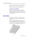
• Maximum wire distance from the MCU to a Base Station (6,000
feet)
• Cabling for the Interface Modules and Controller cards. All cables
(except power) are connected to the front face of the cards. Space
is provided to route wiring to the back of the shelf.
Prepare rack or wall
The SpectraLink 6300 MCU can be mounted in a rack or on the wall.
Rack or wall support must be adequate to support the number of
shelves to be installed. Each fully loaded SpectraLink 6300 MCU shelf
weighs approximately 35 pounds.
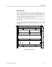
Rack mounting
Before installing shelves in a rack, be sure the rack is mechanically
fastened to the floor or wall such that it properly supports the number