


Site Preparation
PN: 1725-36122-001_M.doc
29
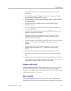
When wiring multiple power pairs, use the following table as a guide.
Pair Function Pin #s
1 Data 1,2
2 PWR 1 7,8
3 PWR 2 4,5
4 PWR 3 6,3
Power pairs are polarity sensitive; pins 7, 4, and 6 must be the same
polarity.
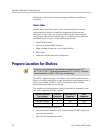
Prepare Demarc Blocks
Interface Modules are designed to operate with a specific interface to
the telephone system: two-wire digital or analog, or four-wire digital
(future release). The number of demarcation blocks required for the
system depends on the number and type of Interface Modules to be
installed.
Interface Type
Interface
Module
Part Number
Wire
Pairs
# Blocks
Analog POTS CPA316 1 1
Universal (Comdial, DEFINITY,
Meridian 1, Norstar, Rolm)
CPU316 1 1
Four-wire digital CPF316 2 2
Mitel (DNIC) CPM316 1 1
Panasonic CPP316 1 1
The CPU316 and CPM316 Interface Modules are intended only for
connection to the isolated-side of an on-premise PBX. These
interfaces are intended to connect to digital PBX ports that provide
signals of 5Vp-p (max) AC component and some PBXs providing a
48Vdc offset.
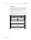
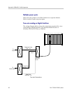
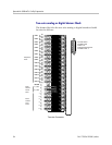
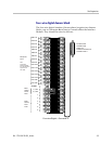
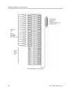
Base Station wiring is the same for all Interface Modules.
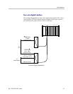
Based on the number and type of interfaces in the system, determine
the number of 25-pair cables required to connect line ports and Base
Stations to the demarcation blocks. The diagrams which follow
provide an overview of the connections.